background image

User Manual

If the yellow LED illuminates in sets of two ashes, this means that the integrated or

external RESET button has been pressed too long. Make sure they are not pressed and then
press any of them, in a quick fashion.

Finally, the red Error LED indicates if there is a problem with the power supply or with

some of the connections to the D-SUB interface. If the red LED ashes (0.1 s on, 0.9 s
o), either there is no robot connected to the power supply or the robot connected is an old
version that is not supported by this power supply. If the red LED illuminates in sets of two
quick ashes, the robot has detected a problem and sent a request to the power supply to
be shut down. If this happens, contact us. If the red LED blinks in regular intervals (0.5 s
on, 0.5 s o), this means that there is either a problem in your external emergency stop or
Stop Category 1 connections or in our power supply. If you don't see any problem in your
connections, contact us. Finally, if the red LED is constantly lit, there is a problem with the
power supply. Switch o the power supply and contact us.

Table summarizes the dierent states of the three LEDs as well as their meanings.

Table 2: The various states of the LEDs on the power supply

LED

Name LED state Explanation

Green

Power

O

The power supply is turned on

On

The power supply is turned o

Yellow Status

O

Robot is not powered. Press RESET.

Blinking

Robot is not powered and a Stop Category 1 stop is pressed or
the dongle is not plugged in. Remove the stop, make sure the
dongle is plugged in, and press RESET.

Two ashes

Robot is not powered because a RESET button has been
pressed for too long. Press RESET again.

On

Robot is powered.

Red

Error

O

There is no error.

Flashes

No proper robot connected.

Two ashes

Robot has detected a problem and requested that power be
shut down. Contact Mecademic.

Blinking

Problem with Stop Category 1 stops detected. Check external
stop connections and contact Mecademic if no solution found.

9.2 External connections

If you do not need to connect an external E-Stop, an external reset, or protective stops or be
able to know whether the robot is powered, you need to plug the D-SUB 15-position dongle

Page 30 of 38

Copyright c

2020 by Mecademic Inc.

Содержание Meca500

Страница 1: ...User Manual Original instructions Meca500 R3 Robot Firmware 8 1 Document Revision B October 15 2020 ...

Страница 2: ...r written approval of Mecademic Inc The information herein is subject to change without notice and should not be construed as a commitment by Mecademic Inc This manual will be periodically reviewed and revised Mecademic Inc assumes no responsibility for any errors or omissions in this document Copyright c 2020 by Mecademic Inc ...

Страница 3: ...nel 13 7 3 1 The status control checkboxes 13 7 3 2 The program editor eld 14 7 3 3 The Response Log eld 15 7 3 4 The Request Log 16 7 4 The robot joint set and end e ector pose panel 16 7 5 The 3D view window 16 7 6 The Quick Command panel 16 7 7 The jogging panel 17 7 7 1 The Joint Jog tab 17 7 7 2 The Cartesian Jog tab 18 7 7 3 The Joystick tab 19 7 8 Opening and closing the MEGP 25 gripper 20 ...

Страница 4: ... Saving the program via the web interface 25 8 4 2 Running an o ine program 25 8 5 Robot control panel 26 8 5 1 LEDs 26 8 5 2 Buttons 27 9 Operating the intelligent power supply 28 9 1 LEDs 29 9 2 External connections 30 10 Installing an end e ector 33 11 Examples 35 11 1 Draw a square 35 12 Troubleshooting 36 13 Storing the robot in its shipping box 37 14 EC Declaration of Incorporation original ...

Страница 5: ...ning messages notes and emphases Particular attention must be paid to the warning messages in this manual There are only two types of warning messages as shown bellow B WARNING This presents instructions that must be followed in order to prevent injuries and possibly damage to your robot cell robot arm power supply end e ector workpiece and or adjacent equipment B CAUTION This presents instruction...

Страница 6: ...fully and do not discard your shipping box If your order contained a gripper do not open its package immediately You must read the MEGP 25 user manual prior to installing the gripper Note that you must provide your own AC power cord with three prong IEC C13 con nector on one end and your own country s power plug on the other You must also provide M6 screws of proper length for xing the robot s bas...

Страница 7: ...he Ethernet and DC power cables provided with longer ones without contacting us rst 4 Safety The Meca500 weighs less than 5 kg It can however move fast and cause injuries especially when certain end e ectors are attached to its ange e g a sharp tool or a laser The robot also has pinch regions where two adjacent links of the robot can squeeze a nger Fig 2 It is imperative that you follow the guidel...

Страница 8: ...connecting an external emergency stop Stop Category 1 a protective stop 1 Stop Category 1 and a protective stop 2 Stop Category 2 The emergency stops and the protective stop 1 are designed as PL d with Safety Category 3 To start using your robot immediately connect the dongle provided to the D SUB 15 position interface This would deactivate the additional protective stops and emergency stop Read s...

Страница 9: ... 2 and 3 This can only be done if the robot is powered AND not activated How to activate and deactivate the robot is explained later in this manual but for now it su ces to say that the robot is deactivated after pressing the E STOP button Thus in case of a collision though ideally prior to that you must press the E STOP button Then to release the brakes of joints 1 2 and 3 press one of the two 0G...

Страница 10: ...nts are at zero degrees in the con guration drawn in black line Also note that the gray zone is the area attainable by the center of the robot s wrist the intersection point of the last three axes for a xed angle of joint 1 This area or even the volume obtained by sweeping this area about the axis of joint 1 is NOT the workspace of the robot The workspace of the robot is a six dimensional entity d...

Страница 11: ...mum power consumption 200 W Input voltage 24 VDC Operating ambient temperature range 5 C 45 C Operating ambient relative humidity range 10 80 non condensing IP rating IP 40 6 Installing the Meca500 You are surely eager to start using your Meca500 It is however imperative that you x solidly the base of your robot arm before activating the robot We typically use metric bread boards such as those fro...

Страница 12: ...s base to allow connection with the 2 meter DC cable provided However unless you are using an external emergency stop wired via the D SUB connector you must x the power supply at a location that makes the integrated E STOP button readily accessible by an operator and outside the working range of the robot The following steps must then be executed before you can start using your Meca500 1 Attach th...

Страница 13: ...its on o button B CAUTION Do not use any other power supply but the one provided or else the warranty will be voided and the CE certi cation no longer valid Always connect the DC power cable before connecting the power supply to an AC outlet Always disconnect the power supply from the AC outlet or switch it o before disconnecting the DC power cable Avoid un plugging the DC power supply too often a...

Страница 14: ...he Ethernet cable and repeat step 1 7 Con gure your computer with a static IP address The way to do this di ers from one operating system to another Figure 6 shows how to do this in Windows and in Linux 8 Open preferably the latest version of Google Chrome and type Meca500 s default IP address 192 168 0 100 in the address bar 9 Meca500 s web interface should load instantaneously If it doesn t repe...

Страница 15: ...x Figure 6 Two examples of how to con gure the IP address of your computer Figure 7 Options dropdown menu a DHCP b Static Figure 8 Two ways to change the robot s network con guration Copyright c 2020 by Mecademic Inc Page 11 of 38 ...

Страница 16: ...ase you also need a third party I O module The web interface is also used for updating the rmware of your robot 7 1 Updating the robot s rmware Before you continue to read any further make sure that you have the latest rmware in stalled on the robot and that you read the manuals corresponding to that rmware Go to https www mecademic com Downloads Updates Robot 20Meca500 R3 and download the most re...

Страница 17: ...own menu in the menu toolbar Menu bar Jogging panel Quick command panel Programming panel Current joint set and TRF pose panel Figure 9 Overview of Meca500 s web interface 7 3 The programming panel The programming panel has two tabs the Main Control and the Request Log tabs 7 3 1 The status control checkboxes Once the web user interface is loaded the rst step is to connect it to the robot So far y...

Страница 18: ...writing and executing very simple programs i e for testing These programs are sequences of the proprietary commands described in the programming manual The robot s command interface does not support conditionals loops or other ow control statements nor variables The robot only accepts request commands to get information from the robot and motion commands to tell the robot to perform an action The ...

Страница 19: ...ntext menu called by pressing the right mouse button when the mouse cursor is over the programming editor Fig 10 Essentially this gives us access to inserting all available commands at the current position of the cursor in the programming editor This functionality is quite similar to the quick command menu with a few di erences The only major di erence is the possibility to insert the commands Mov...

Страница 20: ...x axes are in ref the y axes are in green and the z axes are in blue You can show or hide these two reference frames from the r drop down menu Finally you can choose between several preset views for the 3D view window from the i drop down menu 7 5 The 3D view window The 3D view window shows an orthographic projection of the robot in its current position and the current WRF and TRF To zoom in and o...

Страница 21: ...e corresponding slider as well as the the joint value in both the joint jog tab and the robot posture panel becomes red While joint 6 is limited to 100 rotations its normal operational range is limited to only 180 Speci cally a Cartesian motion command can be executed only if joint 6 is in the 180 range and can remain in that range throughout the whole motion Therefore as soon as joint angle 6 bec...

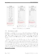
Страница 22: ...TCP if the WRF radio button is selected As in the Joint Jog tab you can select the jog speed and choose to jog both continu ously and incrementally The jog speed in incremental jogging is again constant and set to 100 mm s for linear jogging or 100 s for angular jogging For the incremental jogging you can choose both a linear step from 0 1 mm to 5 0 mm in increments of 0 1 mm and an angular step f...

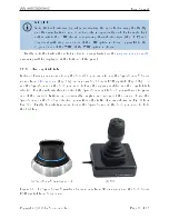
Страница 23: ... the Meca500 you can also use the SpaceMouse R 6 axis mouse from 3Dconnexion Fig 12a or our own MJ3 3 axis USB joystick Fig 12b To use the SpaceMouse or the MJ3 you need to have the jogging enabled and the Joystick tab selected For the web interface to detect the SpaceMouse or the MJ3 you will need to press one of the device s buttons or occasionally unplug and reconnect the device Once the SpaceM...

Страница 24: ...some practice to become comfortable with using all six axes of the SpaceMouse at once Until then you should better use only three axes at a time either translations or rotations To select between all six axes by default translations only or rotations only press up to two times if necessary the left button of the SpaceMouse while holding the Ctrl key until the desired selection is obtained Alternat...

Страница 25: ...less here is a quick summary of the steps that you need to follow in order to power up your robot as described before as well as alternative methods 8 1 1 Powering the robot Turn the power supply on Make sure that the E STOP button on the power supply is released by twisting it counterclockwise and press the RESET button next to it Wait a couple of seconds 8 1 2 Connecting to the robot Connect to ...

Страница 26: ... limitations are not always obvious For example in any six axis robot arm there are often paths that the robot cannot follow even though they seem to be inside the robot s workspace Never forget that the workspace of a general six axis robot is a very intricate six dimensional entity not just a sphere NOTICE If you know nothing about orientation representations and robot singularities we strongly ...

Страница 27: ...eci cally if we consider both frames initially coincident we rotate the second frame about its x axis at α degrees then about its y axis at β degrees and nally about its z axis at γ degrees You can move the robot to the new end e ector pose following these steps Clear the programming text eld type MovePose 250 0 150 0 90 0 and press Ù OR In the quick command panel select MovePose ll in the argumen...

Страница 28: ...o deactivate the robot clear the checkbox OR send the DeactivateRobot command via the programming editor or via the quick command panel B CAUTION Recall that there are no brakes on joints 4 5 and 6 As soon as you deactivate the robot the end e ector will slowly tilt down under the e ects of gravity NOTICE If you accidentally close your web interface before deactivating the robot the robot will sto...

Страница 29: ...buttons on the web interface the robot must be deactivated i e the checkbox must be cleared Write the program in the programming editor To run the program on in nite loop insert the command SetOfflineProgramLoop 1 The õ checkbox has no e ect on the execution of the o ine program Enter 1 as the program id number in the entry eld next to the I button Click on the I button 8 4 2 Running an o ine prog...

Страница 30: ...n state of the robot the LED will ash slowly when the robot is deactivated the LED will ash fast when the robot is being activated the LED will be lit continuously when the robot is activated Home LED The Home LED is yellow and indicates the homing state of the robot the LED will be o when the robot is not homed the LED will ash slowly when the robot is being homed the LED will be lit continuously...

Страница 31: ...he robot except for the 0G button which is always active In what follows you must refer to the detailed descriptions of the commands associated with each button B WARNING When pressing the buttons on the robot s control panel keep your ngers away from the pinch points of the robot and move away from the robot as soon as a button is released Power button The Power button acts as the ActivateRobot a...

Страница 32: ...manually move the robot with your other hand The brakes will reengage as soon as the 0G button is released B CAUTION Once the robot is deactivated hold the robot with one hand before pressing the 0G button Otherwise the robot may fall down under the e ect of gravity 9 Operating the intelligent power supply Mecademic s intelligent power supply is shown in Fig 16 As already explained release all eme...

Страница 33: ...at sup plies voltage at 90 264 V at frequency of 50 60 Hz the green LED next to Power stays illuminated Supplying AC voltage outside this range may damage the power supply Once the power supply is switched on the yellow Status LED indicates the status of the power supply If the yellow LED is o you need to press the RESET button which sends power to the robot If the proper Meca500 is correctly conn...

Страница 34: ... a problem with the power supply Switch o the power supply and contact us Table 2 summarizes the di erent states of the three LEDs as well as their meanings Table 2 The various states of the LEDs on the power supply LED Name LED state Explanation Green Power O The power supply is turned on On The power supply is turned o Yellow Status O Robot is not powered Press RESET Blinking Robot is not powere...

Страница 35: ...top Category 2 protective stop connections P Stop 2 A P Stop 2 B Note that the external circuits shown in Fig 17 are only suggestions You may for example connect several external E Stops in series or instead of sending a signal to a PLC when the power to the robot is cut you may connect a LED between the resistor and the Power Status A line Figure 18 shows several other examples Speci cally Fig 18...

Страница 36: ...Stop 1 A1 P Stop 1 K1 P Stop 1 K2 P Stop 2 K Reset K External reset Inside power supply Inside power supply Vin External protective stop 1 Stop Category 1 P Stop 1 A1 4 P Stop 1 K1 12 P Stop 1 A2 5 P Stop 1 K2 13 Inside power supply P Stop 2 A 6 P Stop 2 K 14 External protective stop 2 Stop Category 2 Inside power supply R R R R R Vin Vin Vin Vin Figure 17 Electric diagram of suggested generic con...

Страница 37: ...of connections to D SUB connector 10 Installing an end e ector The Meca500 comes with a proprietary tool I O input output port located at the robot extremity Fig 19a However this tool port is reserved uniquely for our electric gripper MEGP 25 We do not share the pinout of this port or its custom made communication protocol To install our gripper refer to its user manual If you want to use any othe...

Страница 38: ...o follow the procedure described in the subsection Homing of the programming manual a Closeup Ø20 units mm Ø9 H6 É2 2 M3X0 5 É4 BCD 15 5 4X equally spaced Ø3 É3 5 BCD 15 5 2X equally spaced b Dimensions Figure 19 The mechanical interface ange of the Meca500 The ange is the 20 disk inside the black isolation ring and is the only one to rotate when joint 6 rotates B CAUTION Make sure that joint 6 is...

Страница 39: ...MoveLin 270 100 250 0 90 0 MoveLin 270 100 250 0 90 0 MoveLin 140 100 250 0 90 0 MoveJoints 0 0 0 0 0 0 Figure 20 shows the result of each of the rst four motion commands a MovePose 140 100 250 0 90 0 b MoveLin 140 100 250 0 90 0 c MoveLin 270 100 250 0 90 0 d MoveLin 270 100 250 0 90 0 Figure 20 The four separate robot positions that de ne the motion sequence Copyright c 2020 by Mecademic Inc Pag...

Страница 40: ...ke sure that the robot s IP default address 192 168 0 100 does not con ict with any other device on the network For example Robot IP 192 168 0 100 netmask 255 255 255 0 gateway 192 168 0 1 Computer IP 192 168 0 101 netmask 255 255 255 0 gateway 192 168 0 1 If you are using DHCP make sure to verify the robot s IP address through your router s web interface Robot fails to boot Disconnect the power s...

Страница 41: ...nd the sequence of numbers displayed after Meca500 R3 in the welcome message that appears in the log panel upon connection with the robot 3000 Connected to Meca500 R3 v8 x x This is the rmware version installed on your robot You can also get that number by executing the command GetFwVersion 13 Storing the robot in its shipping box To put the Meca500 back into the foam insert of its original shippi...

Страница 42: ...achinery Directive 2006 42 EC and with the regulations transposing it into national law Compliance with all essential requirements of Directive 2006 42 EC relies on the speci c robot installation and the nal risk assessment The manufacturer agrees to forward on demand the relevant technical documentation compiled according to Directive 2006 42 EC Annex VII Part B to state authorities Additionally ...

Страница 43: ......

Страница 44: ...Mecademic Inc 1300 Saint Patrick St Montreal QC H3K 1A4 CANADA ...

Отзывы: