User Manual
135
135
38
120
70
R260
boundary for
wrist center
45
units: mm
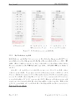
Figure 3: The dimensions of the Meca500
Note that the robot will automatically detect the angle between the axis of joint 1 and
the gravity vector. Also, note that you can mount the robot's base on a mobile body (e.g.,
on the carriage of a linear guide), but only if you do not intend to move the robot's joints,
while the robot's base is moving with respect to the ground.
Next, you must solidly attach the power supply using four M6 screws (Fig. 5), at a
location suciently close to the robot's base to allow connection with the 2-meter DC cable
provided. However, unless you are using an external emergency stop wired via the D-SUB
connector, you must x the power supply at a location that makes the integrated E-STOP
button readily accessible by an operator and outside the working range of the robot.
The following steps must then be executed before you can start using your Meca500:
1. Attach the circular connector of the Ethernet cable to the ETHERNET1 port on the
robot's base and connect the RJ-45 jack to your computer or router (Fig. 4b-c). The
two Ethernet ports on the robot's base act as a bridge, so you can daisy-chain several
Meca500 robots, or connect an Ethernet I/O module on the ETHERNET2 port.
Page 8 of 38
Copyright c
2020 by Mecademic Inc.


