background image


USB-2404-UI 

USB-based Universal Analog Input Device 

Document Revision 2 
March 2012 
© Copyright 2012 

User's Guide 

Distributed by MicroDAQ.com, Ltd.                   www.MicroDAQ.com                   (603) 746-5524

Содержание USB-2404-UI

Страница 1: ...USB 2404 UI USB based Universal Analog Input Device Document Revision 2 March 2012 Copyright 2012 User s Guide Distributed by MicroDAQ com Ltd www MicroDAQ com 603 746 5524...

Страница 2: ...oduct by mistake you do not have to keep it These warranties are in lieu of all other warranties expressed or implied including any implied warranty of merchantability or fitness for a particular appl...

Страница 3: ...er 3 Functional Details 10 Components 10 Spring terminal connectors 10 Strain relief slot 11 USB connector 11 LED 11 Connecting wires to the spring terminals 11 TEDS sensor connections 12 Signal sourc...

Страница 4: ...I User s Guide 4 Environmental 19 Mechanical 19 Safety voltages 19 Spring terminal connectors 19 Accessory products 20 Declaration of Conformity 21 Distributed by MicroDAQ com Ltd www MicroDAQ com 603...

Страница 5: ...946 5100 and follow the instructions for reaching Tech Support Fax 508 946 9500 to the attention of Tech Support Email techsupport mccdaq com Hazardous voltages You can connect hazardous voltages to t...

Страница 6: ...and 2 wire Bridge based sensors quarter half and full bridge Measurement ranges vary for each type of measurement The device features built in current and voltage excitation The excitation circuit is...

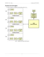
Страница 7: ...oducing the USB 2404 UI 7 Functional block diagram USB 2404 UI functions are illustrated in the block diagram shown here Figure 1 USB 2404 UI functional block diagram Distributed by MicroDAQ com Ltd w...

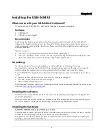
Страница 8: ...ject to eliminate any stored static charge If your USB 2404 UI is damaged notify Measurement Computing Corporation immediately by phone fax or e mail Phone 508 946 5100 and follow the instructions for...

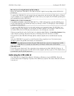
Страница 9: ...t the device for the first time to a computer running Windows a Found New Hardware dialog opens when the operating system detects the device The dialog closes after the device is installed The green L...

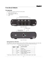
Страница 10: ...or four analog input channels The signal names for the spring terminal in each connector are listed in the table below 6 terminal connector signal names Terminal number Signal name Signal description...

Страница 11: ...The voltage supplied through the USB connector is system dependent and may be less than 5 V No external power supply is required LED The LED indicates the device status When connected to a USB port th...

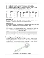
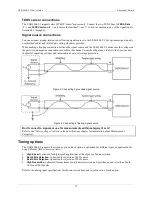
Страница 12: ...out overvoltage protection Figure 5 Connecting a grounded signal source Figure 6 Connecting a floating signal source Don t connect to signals or use for measurements within category III or IV Refer to...

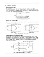
Страница 13: ...terminals The current is computed from the voltage that the ADC measures across an internal shunt resistor Voltage and current mode connections are shown in Figure 8 Figure 8 Voltage and current mode...

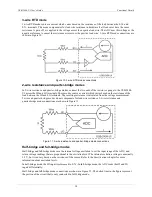
Страница 14: ...The resulting resistance is calculated from the voltage measurement 2 wire and quarter bridge modes do not compensate for lead wire resistance 2 wire resistance and quarter bridge mode connections are...

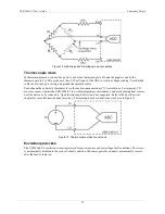
Страница 15: ...CJC sensor accuracy operate the USB 2404 UI in a stable temperature environment and avoid placing heat sources near the device or its connectors Open thermocouple detection is not supported Refer to...

Страница 16: ...l channels High resolution 500 ms for all channels Conversion time One or more channels in TC mode High speed 20 ms for all channels Best 60 Hz rejection 120 ms for all channels Best 50 Hz rejection 1...

Страница 17: ...0 1 0 5 240 640 4 wire and 3 wire RTD Pt 100 0 1 0 5 2400 6400 Quarter bridge 350 0 1 0 5 2400 6400 Quarter bridge 120 0 1 0 5 2400 6400 Half bridge 500 mV V 0 03 0 07 300 450 Full bridge 62 5 mV V 0...

Страница 18: ...00 7 6 1 7 1 1 0 4 4 wire and 3 wire RTD Pt 100 10 8 1 9 1 9 0 9 Quarter bridge 350 5 4 1 0 1 0 0 7 Quarter bridge 120 5 4 1 0 1 0 0 7 Half bridge 500 mV V 3 8 0 5 0 5 0 2 Full bridge 62 5 mV V 5 4 1...

Страница 19: ...Parameter Conditions Specification Channel to earth ground isolation Continuous 250 VAC Measurement Category II Note 3 Withstand 2300 VAC verified by a 5 second dielectric withstand test Channel to ch...

Страница 20: ...de Input mode Signal terminals 1 2 3 4 5 6 Voltage T T HI LO Current T T HI LO 4 wire resistance T T EX HI EX LO 2 wire resistance T T HI LO Thermocouple T T HI LO 4 wire RTD T T EX HI EX LO 3 wire RT...

Страница 21: ...to the standards of this declaration the following conditions must be met The host computer peripheral equipment power sources and expansion hardware must be CE compliant All I O cables must be shield...

Страница 22: ...nt Computing Corporation 10 Commerce Way Suite 1008 Norton Massachusetts 02766 508 946 5100 Fax 508 946 9500 E mail info mccdaq com www mccdaq com Distributed by MicroDAQ com Ltd www MicroDAQ com 603...

Отзывы: