www.procontechnology.com.au
4 Phone: (03) 98306288
3. INSTALLATION, WIRING AND OPERATION
Even the most efficient switched mode DC-DC converter will not function properly if the installation, wiring or connections are
incorrect. Follow the installation, wiring and connection instructions specified in the data sheet or manual before switching on
any unit. Also see the document 'Power Supply Cables and Connectors' (Meanwell_Connect_Safety.pdf).
3.1 INSTALLATION
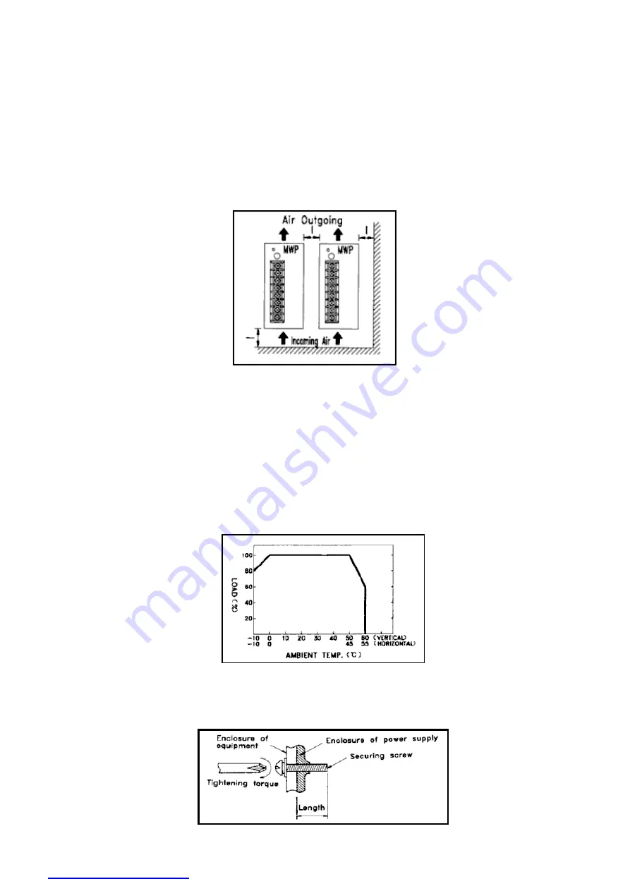
Heat Dissipation
a. Ensure the unit is properly ventilated.
b. Install the unit in the correct position. Remember 'hot air rises' and ensure correct orientation.
c. Ensure the unit has proper heat conduction and is not mounted near other heat sources.
d. When you install two or more units, leave additional space between them for cooling.
e. Forcing air over the unit will improve heat dissipation.
Fig. 6
When mounting any device please refer to any notes and temperature derating curves in the specifications. For example with
DIN rail converters, the minimum installation clearances are: 40mm on top, 20mm on the bottom, 5mm on the left and right
sides unless the adjacent device is also a heat source then 10-15mm clearances are recommended.
Output Derating
Output power depends on operating temperature. Derate the output of the DC-DC converter according to the temperature
derating curve shown in the specifications. The Railway DC-DC converter series (RSD) when mounted on an iron plate of
sufficient size allows for the elimination of any derating up to its' maximum operating temperature of 70°C. Note the output
power may also need to be derated with low input voltages. Specifications cannot be guaranteed when under-voltage. Some
units will shut down on under-voltage.
Fig. 7
Securing Screws
Always check the specified screw length and tightening torque when attaching to your equipment enclosure.
Fig. 8
See the mechanical
specifications in the data
sheet. Length L=? is in
millimetres.


