


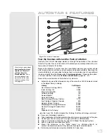


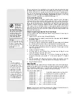


Caution:
Use care to install batteries as indicated by the battery
compartment. Follow battery manufacturer's precautions. Do not install
batteries backwards or mix new and used batteries. Do not mix battery
types. If these precautions are not followed, batteries may explode, catch
fire, or leak. Improperly installed batteries void your Meade warranty.
Always remove the batteries if they are not to be used for a long period of
time.
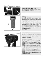
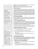
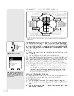
To attach AutoStar II and connect the handbox holder
1.
Plug in the AutoStar II handbox:
Check that the power switch on the computer
control panel (
12, Fig. 16
) is in the OFF position. Plug the coil cord of the AutoStar
II handbox into the HBX port of the base control panel (
13, Fig. 16
) or the HBX
port of the OTA control panel (
M, Fig. 1e
).
Note:
The AutoStar II handbox does not require batteries; the batteries in
the telescope supply the power.
Note:
You can only plug one handbox into the telescope at a time; you
cannot plug in two handboxes into the two control panels at the same time.
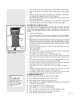
2.
Attach the handbox holder:
Remove the handbox holder from the plastic bag. If
necessary, loosen the lock knob (
14, Fig. 17a
) and place the clamp (
15, Fig. 17a
)
about one of the fork arm handles (
15, Fig. 1a
). Tighten the lock knob to a firm
feel. Slide the AutoStar II handbox into the holder (
16, Fig. 17a
).You may also
snap the handbox into the holder: Slide one side of the handbox into the holder
and then firmly press the other side of the handbox into the holder until it snaps
in place. Adjust the tilt of of the holder by loosening the lock knob and then mov-
ing the holder clamp to the desired angle. Retighten the lock knob.
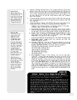
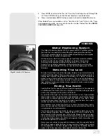
To attach the diagonal mirror and the eyepiece
1.
Attach Visual back and Diagonal mirror: Thread the ring of the visual back over
the rear cell and rotate the ring, tightening to a firm feel (see
Figs. 18 and 19
) .
Slide the diagonal into the visual back and secure it in place using the visual back
thumbscrew.
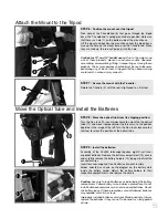
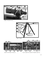
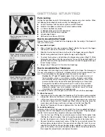
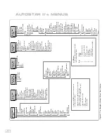
Fig. 15:
Battery installation.
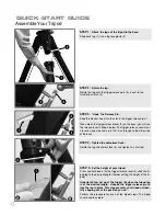
Fig. 12:
Line up the T-handle rod (8)
with the hole on the base (7).
Fig. 13:
Tighten the T-handle (9) to a
“firm feel.”
Fig. 14:
Loosen the R.A. (11) and
Dec. (10) locks to Move the optical
tube from its shipping position.
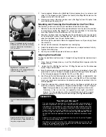
Fig. 17a:
Handbox holder: (14) Lock
knob; (15) Clamp; (16) Holder.
Fig. 17b:
Handbox holder attached to
fork arm handle.
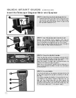
Fig. 18:
Rear cell
(17).
Fig. 19:
Thread the ring of the
visual back (18) onto the rear
cell (17). Slide diagonal into the
visual back and secure with
thumbscrew (19).
Fig. 20
: Slide eyepiece (20)
into the diagonal mirror and
tighten thumbscrew (21).
Fig. 16:
Locations of the On/Off switch and the
HBX port on the Computer Control Panel locat-
ed on the base of the telescope.
h
i
j
1)
1!
1$
1%
1^
1*
1(
1&
2)
2!
17
1@
1#
1&
A
B
Содержание RCX400
Страница 73: ......