background image

Installation Manual

IM 676

Group: Chiller

Part Number: 594920Y

Date: July 1996

Supersedes: None

© 1996 McQuay International

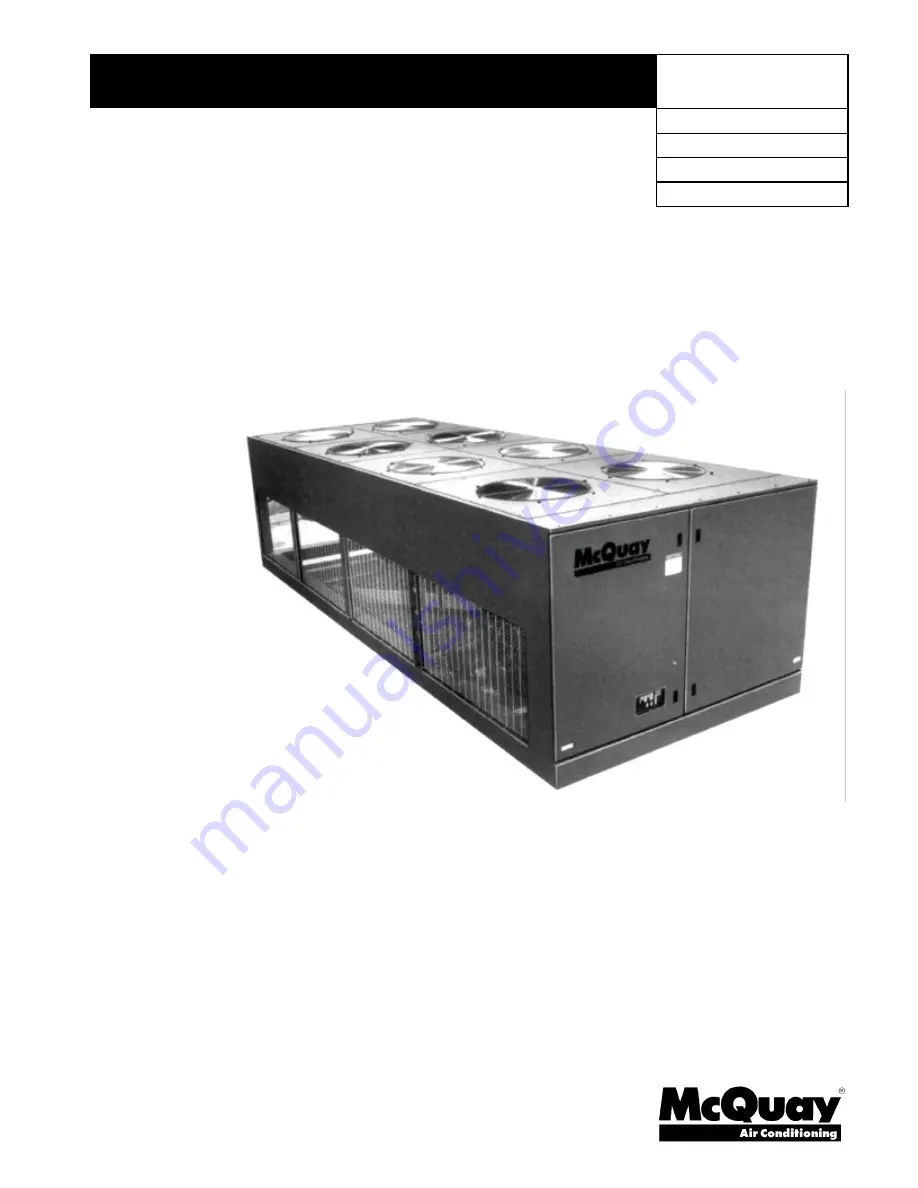
SeasonPak
Packaged Air-Cooled Water Chiller

Models ALR 032E Through 185E

Содержание ALR 032E

Страница 1: ...Installation Manual IM 676 Group Chiller Part Number 594920Y Date July 1996 Supersedes None 1996 McQuay International SeasonPak Packaged Air Cooled Water Chiller Models ALR 032E Through 185E...

Страница 2: ...rs 6 Water Piping 7 Flow Switch 8 Water Connections 8 Refrigerant Charge 9 Glycol Solutions 9 Evaporator Water Flow and Pressure Drop 10 Physical Data 12 Electrical Data 18 Field Wiring 18 Dimensional...

Страница 3: ...started by their own three pole contactors Compressors are not fused but may be protected by optional circuit breakers or by a field installed fused disconnect Inspection Check all items carefully ag...

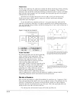
Страница 4: ...lab with footings extended below the frost line is recommended Be sure the foundation is level within 1 2 13 mm over its length and width The foundation must support the operating weights listed in th...

Страница 5: ...uitable for most applications When additional sound reduction is necessary locate the unit away from sound sensitive areas Avoid locations beneath windows or between structures where normal operating...

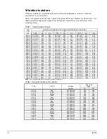
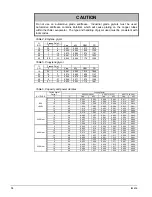
Страница 6: ...75 669 100E CP 2 28 1193 541 CP 2 28 1214 551 CP 2 31 1508 684 110E CP 2 28 1339 607 CP 2 28 1364 619 CP 2 31 1697 770 120E CP 2 31 1362 618 CP 2 31 1490 676 CP 2 32 1748 793 130E CP 2 31 1492 677 CP...

Страница 7: ...e to prevent freeze up down to 20 F 29 C It is suggested that the heating cable be wired to a separate 110V supply circuit As shipped from the factory the heating cable is wired to the control circuit...

Страница 8: ...exists Freeze protect any flow switch that is installed outdoors NOTE Differential pressure switches are not recommended for outdoor installation Table 3 Flow switch minimum flow rates NOMINAL PIPE SI...

Страница 9: ...y Glycol GPM from table 24 capacity glycol Delta T G For Metric Applications To determine evaporator L s or Delta T knowing Delta T or L s and kW Glycol L s from table kW Delta T Flow 4 18 3 Pressure...

Страница 10: ...Cap kW 6 3 3 0 992 0 995 0 996 0 982 0 911 0 935 8 4 4 0 995 0 997 0 969 0 984 0 914 0 937 SEA 10 5 6 1 000 1 000 0 975 0 986 0 919 0 939 LEVEL 12 6 7 1 005 1 002 0 980 0 989 0 923 0 941 14 6 8 1 010...

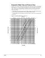
Страница 11: ...xpansion valve and could cause low temperature cutouts Flow rates exceeding the maximum values can cause erosion on the evaporator water connections and tubes Measure the chilled water pressure drop t...

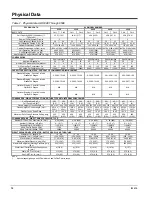
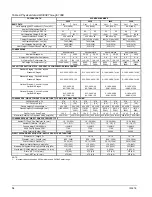
Страница 12: ...N A N A Optional Staging Circuit 2 in Lead Optional 6 Stages N A N A N A N A N A CONDENSERS HIGH EFFICIENCY FIN AND TUBE TYPE WITH INTEGRAL SUBCOOLING Coil Face Area Sq Ft 28 3 28 3 28 3 28 3 28 3 28...

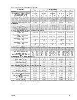
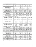
Страница 13: ...0 67 83 100 Optional Staging Circuit 2 in Lead Optional 6 Stages 0 17 33 50 67 83 100 0 18 33 51 67 85 100 0 17 33 50 67 83 100 0 17 33 51 67 84 100 0 17 33 50 67 83 100 CONDENSERS HIGH EFFICIENCY FIN...

Страница 14: ...48 0 19 39 48 58 0 18 36 45 76 63 75 88 100 60 76 88 100 69 81 90 100 68 82 91 100 Optional Staging Circuit 2 in Lead Optional 8 Stages 0 13 25 38 50 0 12 24 36 48 0 19 39 48 58 0 18 36 45 76 63 75 8...

Страница 15: ...0 17 33 42 50 0 16 32 40 48 64 84 92 100 67 84 91 100 67 83 92 100 66 84 92 100 Optional Staging Circuit 2 in Lead Optional 8 Stages 0 16 32 40 48 0 17 32 41 48 0 17 33 42 50 0 16 32 40 48 68 84 92 10...

Страница 16: ...2 50 0 17 33 42 50 0 15 32 40 64 0 17 33 42 50 67 83 92 100 67 83 92 100 64 84 92 100 63 71 86 100 Optional Staging Circuit 2 in Lead Optional 8 Stages Std on MicroTech Units 0 17 33 42 50 0 17 33 42...

Страница 17: ...on MicroTech Units 0 19 37 44 50 0 17 34 40 46 0 19 37 44 50 62 75 87 100 67 89 94 100 62 75 87 100 Optional Staging Circuit 2 in Lead Optional 8 Stages Std on MicroTech Units 0 19 37 44 50 0 17 34 40...

Страница 18: ...ion is ordered a single large power terminal block is provided and wiring within the unit is sized in accordance with the National Electrical Code A single field supplied fused disconnect is required...

Страница 19: ...1 25 32 125 150 575 89 3 3 1 1 25 32 110 125 208 228 3 4 0 1 2 00 51 300 300 230 228 3 4 0 1 2 00 51 300 300 050E 460 60 113 3 2 1 1 25 32 150 150 575 94 3 3 1 1 25 32 110 125 208 238 3 250 1 2 50 64...

Страница 20: ...00 51 225 225 575 165 3 2 0 1 1 50 51 200 200 208 424 6 300 1 4 00 102 450 500 230 424 6 300 1 4 00 102 450 500 100E 460 60 210 3 4 0 1 2 00 51 225 250 575 175 3 2 0 1 1 50 51 200 200 208 494 6 350 1...

Страница 21: ...800 800 230 653 6 500 2 3 00 76 800 800 150E 460 60 328 3 400 1 3 00 76 350 450 575 257 3 300 1 2 50 64 300 300 208 716 6 500 2 3 00 76 800 800 230 700 6 500 2 3 00 76 800 800 160E 460 60 352 3 500 1...

Страница 22: ...0 51 125 150 93 3 3 1 2 00 51 125 150 040E 460 60 8 5 3 14 1 75 19 15 15 47 3 8 1 1 25 32 60 80 47 3 8 1 1 25 32 60 80 575 9 4 3 14 1 75 19 15 15 39 3 8 1 1 25 32 50 60 39 3 8 1 1 25 32 50 60 208 25 3...

Страница 23: ...s and Transformer Electrical Circuit 2 Compressor Circuit 1 Electrical Circuit 3 Compressor Circuit 2 ALR Min Power Supply Field Fusing Min Power Supply Field Fusing Min Power Supply Field Fusing Unit...

Страница 24: ...00 25 30 30 95 3 3 1 1 25 32 110 125 95 3 3 1 1 25 32 110 125 208 71 3 4 1 2 00 51 80 80 290 3 350 1 2 50 64 350 400 290 3 350 1 2 50 64 350 400 230 71 3 4 1 2 00 51 80 80 271 3 300 1 2 50 64 350 350...

Страница 25: ...3 00 76 400 400 160E 460 60 40 3 8 1 1 25 32 40 40 167 3 2 0 1 2 00 51 200 225 167 3 2 0 1 2 00 51 200 225 575 33 3 10 1 1 00 25 35 35 133 3 1 0 1 1 50 38 175 200 133 3 1 0 1 1 50 38 175 200 208 83 3...

Страница 26: ...6 8 5 214 283 132 156 575 31 36 2 2 6 10 3 172 230 103 138 208 85 95 4 0 6 17 0 470 565 292 340 230 85 95 4 0 6 17 0 470 565 292 340 050E 460 60 42 47 2 0 6 8 5 235 283 141 156 575 36 36 2 2 6 10 3 2...

Страница 27: ...470 470 340 340 292 292 230 95 95 85 85 4 0 10 17 0 565 565 470 470 340 340 292 292 100E 460 60 47 47 42 42 2 0 10 8 5 283 283 235 235 156 156 141 141 575 36 36 36 36 2 2 10 10 3 230 230 200 200 138...

Страница 28: ...297 510 195 195 195 330 575 48 48 48 68 2 3 12 11 5 245 245 245 405 152 152 152 262 208 135 135 162 162 5 8 14 23 7 754 754 1070 1070 463 463 654 654 230 127 127 162 162 5 8 14 21 4 594 594 1070 1070...

Страница 29: ...1 qty 14 1 0 208 335 1 qty 4 400 MCM 400 1 qty 250 500 MCM 230 335 1 qty 4 400 MCM 400 1 qty 250 500 MCM 050E 460 60 335 1 qty 4 400 MCM 150 1 qty 4 4 0 575 335 1 qty 4 400 MCM 100 1 qty 14 1 0 208 3...

Страница 30: ...50 MCM 575 335 1 qty 4 400 MCM 250 1qty 4 350 MCM 208 840 2 qty 1 0 600 MCM 600 2 qty 250 500 MCM 230 840 2 qty 1 0 600 MCM 600 2 qty 250 500 MCM 100E 460 60 335 1 qty 4 400 MCM 250 1qty 4 350 MCM 575...

Страница 31: ...0 600 MCM 400 1 qty 250 500 MCM 575 840 2 qty 1 0 600 MCM 400 1 qty 250 500 MCM 208 840 4 qty 1 0 600 MCM N A 230 840 4 qty 1 0 600 MCM N A 160E 460 60 840 2 qty 1 0 600 MCM 400 1 qty 250 500 MCM 575...

Страница 32: ...175 335 335 1 qty 12 2 0 1 qty 4 400 MCM 1 qty 4 400 MCM 050E 460 60 175 175 175 1 qty 12 2 0 1 qty 12 2 0 1 qty 12 2 0 575 175 175 175 1 qty 12 2 0 1 qty 12 2 0 1 qty 12 2 0 208 175 335 335 1 qty 12...

Страница 33: ...2 2 0 208 175 335 335 1 qty 12 2 0 1 qty 4 400 MCM 1 qty 4 400 MCM 230 175 335 335 1 qty 12 2 0 1 qty 4 400 MCM 1 qty 4 400 MCM 135E 460 60 175 175 175 1 qty 12 2 0 1 qty 12 2 0 1 qty 12 2 0 575 175 1...

Страница 34: ...ed power lead wire sizes are based on an ambient temperature of 86 F Ampacity correction factors must be applied for other ambient temperatures Refer to the National Electrical Code Handbook Voltage L...

Страница 35: ...IM 676 35 Figure 7 ALR 032E through 185E typical field wiring diagram...

Страница 36: ...27 98 4 2499 13 0 330 28 6 726 15 9 404 77 0 1956 41 7 1059 13 330 58 1473 162 4115 6 060E 176 4470 5 127 98 4 2499 13 0 330 28 6 726 15 9 404 77 0 1956 41 7 1059 13 330 58 1473 162 4115 6 065E 176 44...

Страница 37: ...7 41 7 1059 13 330 58 1473 215 5461 12 140E 229 5817 6 152 4 118 5 3010 12 9 328 19 5 495 108 0 2743 41 7 1059 13 330 58 1473 215 5461 12 145E 229 5817 6 152 4 118 5 3010 12 9 328 20 5 521 103 0 2616...

Страница 38: ...high voltage and low voltage All high voltage components are located in the compartment on the right side of the unit The low voltage components are located on the left side with the live terminals be...

Страница 39: ...Note PB1 PB2 PB3 are used with multiple point power wiring Figure 15 Recommended field installed unit disconnect location Note Mount disconnect on stationary panel so it does not interfere with hinged...

Страница 40: ...main power and control disconnect switches This will energize crankcase heaters Wait at least 12 hours before starting up unit 11 Open all water flow valves and start the chilled water pump Check all...

Страница 41: ...time clock or manual shutdown switch turns on the chilled water pump the flow switch closes and 115V power is applied to the relay contacts on the leaving water control LWC1 The unit will automatical...

Страница 42: ...control s LP1 and LP2 will open If the refrigerant leaks into the low side causing the pressure to close the low pressure controls LP1 and LP2 the compressor will start after a two hour time delay For...

Страница 43: ......

Страница 44: ...13600 Industrial Park Boulevard P O Box 1551 Minneapolis MN 55440 USA 612 553 5330...

Отзывы: