MCi JH-400B Series Скачать руководство пользователя страница 1

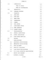
Содержание JH-400B Series

Страница 1: ...L I ___ I TECHNICAL MANUAL JH 4008 SERIES CONSOLE r 1 I J PRINTED January 1 1978 MCI INC 4007 N E 6th AVENUE FORT LAUDERDALE FLORIDA 33334 USA TELEPHONE 305 566 2853 TELEX 514 362 MCI FTL...

Страница 2: ...I I 1 I INTRODUCTION...

Страница 3: ...und No discussion of design problems or solutions is included since such information although interesting does not contribute to the purpose of this manual The sectional tabs allow quick location of a...

Страница 4: ...BLESHOOTING 7 0 8 0 9 0 10 0 6 1 6 2 6 3 8 1 8 2 8 3 8 4 8 5 8 6 GENERAL INSTRUCTIONS SIGNAL SUBSTITUTION LIGHT lliTER SERVICING OPTIONS SPECIFICATIONS ELECTRONIC SPECIFICATIONS MECHANICAL SPECIFICATI...

Страница 5: ...11 0 13 0 Page 1 4 13 1 13 2 SPARE PARTS LISTS 11 1 INSTALLATION 13 1 PUNCH BLOCK CONNECTIONS 13 1 GROUND RULES FOR GROUNDING A RECORDING SYSTEH 13 1A JH 400B...

Страница 6: ...SWITCH BLOCK DIAGRAM PRODUCING FEEDBACK LOOP 3 4 12 ECHO SWITCH BLOCK DIAGRAM PRODUCING NO FEEDBACK LOOP 3 5 13 JH 400B LIGHT METER BLOCK DIAGRAM 3 10 14 JH 400B FLOW CHART 3 7 15 MOTHER BOARD LOCATIO...

Страница 7: ...i DESCRIPTION I...

Страница 8: ...ge swing allows more headroom than most consoles in spite of the higher program level With a program level 6db above the usual level the signal to noise ratio is improved and the RF rejection on all s...

Страница 9: ...A sufficient number of switch points is provided to allow selection of the exact amount of EQ required Switches used for all circuits allow EXACT reproduction of any EQ previously used 6 The JH 400B C...

Страница 10: ...OPERATION...

Страница 11: ...switch and a feed to the ECHO switch Each I 0 module contains ONE CHANNEL ACN which is the outout amplifier for the CH NEL BUS having the same number as the I 0 module In addition to feeding the TAPE...

Страница 12: ...de the TAPE RETURN LINE monitors the output of the PLAY head ANY INDIVIDUAL 1 0 f 10DULE CAN BE SWITCHED BACK TO MIKE MODE FROM TAPE MODE BY PRESSING THE f 10N BUTTON THIS fv1UST BE DONE IN OVERDUBS I...

Страница 13: ...omplete the only change needed is to switch the tape machine back to PLAY mode 3I 5 SUMt 1ARY MIKE mode occurs when both the MONITOR relays and the REMIX relays are inactive This mode is used for prel...

Страница 14: ...ch to allow ECHO o be recorded on the MASTER TAPE When recording ECHO feedback loop may be formed unless the FEED POINT to the ECHO SEND is chosen carefully The following BLOCK DIAGRAMS show the probl...

Страница 15: ...es a separate POWER SUPPLY a MASTER COJ JTROL BOARD and v qne CHANNEL BOARD for each meter The MASTER CONTROL BOARD generates the precision RA 1P which is used on each CHANNEL BOARD to measure the AUD...

Страница 16: ...ivalent to the AUDIO LEVEL This level is compared to the RAMP coming from the MASTER CONTROL BOARD When the RAMP exceeds the AUDIO SIGNAL level the cm1PARATOR output switches to the positive rail and...

Страница 17: ...unter l RAMP OUTPUT _____j 4 BCD 0 OUTPUT I I I I I I I L ____ _ _J r I I I I I I I RAMP INPUT AUDIO J NPUT BCD INPUT Precision I Rectifier Comparator l Latch I j 1 l L Decoder I i I I I I I I I L ___...

Страница 18: ...TROUBLESHOOTING...

Страница 19: ...e JH 400B They are fully explained on pages 3 1 through 3 3 of this manual FOLLOW THE SIGNAL FLOW FOR EACH MODE B Be sure that you know the ORDER in which the signal passes through each FUNCTION i e C...

Страница 20: ...e 4 Adjust the oscillator level for 4 dBv output level at the channel line output of the channel being calibrated 5 Connect an oscilloscope to pin 6 of IC2 on the Channel Board being calibrated This i...

Страница 21: ...I L OPTIONS...

Страница 22: ...of 8 joystick panners Up to 7 additional joystick panners installed as Option 6 specify quantity each Extra length power supply cables per foot per cable over 30 feet Note JH 428B JH 440B VU frames to...

Страница 23: ...SPECIFICATIONS...

Страница 24: ...IN HAX 24dBv 24dBv 22dBv 22dBv 22dBv HEADROOM 30dBv 23dBv 24dBv 18dBv l8dBv Measured Mike input to channel line output with a 150 ohm source impedence and lOk ohm output termination 72 dB CROSSTALK Cr...

Страница 25: ...HT JH 428VU 199 kilograms 439 lbs JH 428LM 264 kilograms 582 lbs JH 440VU 290 kilograms 640 lbs JH 440LM 310 kilograms 683 lbs Console Power 12 25 kilograms Supplies 3 req d 27 lbs Light Meter 6 8 kil...

Страница 26: ...utput trans Inserts signal into the multitrack tape input In addition to the above patch points for each channel the following REMIX and Console function patch points are available QUAD MIX OUTPUT 1 4...

Страница 27: ...TUm 102 milliseconds The SCAN TIME is NOT a delay and does NOT accumulate BOUNCE DELAY 1 2ms per pass The BOUNCE DELAY IS a delay which accumulates with each UPDATE pass DATA RATE 9600 Baud 14kHz band...

Страница 28: ...l l l L L l L l l WARRANTY...

Страница 29: ...ers LIMITATIONS All warranties either written or implied are void if this equipment was assembled or installed by anyone other than an MCI approved dealer MCI s obligation is limited to repairing or r...

Страница 30: ...SCHEMATICS...

Страница 31: ...MODULE 26 SPECTRA VUE HODULE 27 POWER SUPPLY 28 L M CHANNEL BOARD 29 L M MASTER CONTROL BOARD 30 L M POWER SUPPLY 31 ALTERNATE SPEAKER RELAY 32 L M BUFFER BOARD JH 400B DRAWING NO 43E241 43D97 43D96 4...

Страница 32: ......

Страница 33: ......

Страница 34: ......

Страница 35: ......

Страница 36: ......

Страница 37: ......

Страница 38: ......

Страница 39: ......

Страница 40: ......

Страница 41: ......

Страница 42: ......

Страница 43: ......

Страница 44: ......

Страница 45: ...SPARE PARTS...

Страница 46: ...or a JH 400B console with BOTH light meter option and with JH 50 400B Automation option KIT NO 4300 0117 00 NO 1 1 1 2 2 1 1 1 1 1 1 1 1 6 2 1 2 2 1 1 1 2 1 2 1 1 2 1 1 1 PART NO MJE105 MJE205 NPC139...

Страница 47: ...03P TL081 TL082 MV5075 MV5274C MV5374C SWA 0034 Page 11 2 DESCRIPTION Transistor Transistor Quad op amp Hex buffer BCD decoder driver Monostable Multivibrator One shot Quad D flip flop 4 bit up down c...

Страница 48: ...P 7000 0160 02 F4UEE F8UEE MST 205N 01 282 SPA7000 0164 0l SPA7000 0165 0l SPA7000 0166 01 AZ521 07 10 RA30321911 02 SP7000 0106 00 SP7000 0108 00 SP7000 0125 00 DESCRIPTION Transistor Transistor Tran...

Страница 49: ...I INSTALLATION I i I...

Страница 50: ...put 20 Hultitrack Machine 1 Input 20 Hike Input 21 Multitrack 1achine 1 Input 21 Mike Input 22 Multitrack Machine 1 Input 22 Mike Input 23 1ul ti track Machine 1 Input 23 Mike Input 24 Multitrack Mach...

Страница 51: ...Line Tie Line Tie Line 3 JH 428B Page 13 2 1 2 3 4 5 6 7 8 9 0 10 g 11 g 12 13 rt 14 15 1 16 e 17 g 18 tl1 19 t i 20 c 21 I 22 N 23 co 24 25 26 27 28 23 24 tl1 t i 25 26 I 29 30 31 32 33 34 N 35 f 36...

Страница 52: ...i Tie Line 82 Tie Line 83 Tie Line 84 Tie Line 85 Tie Line 86 Tie Line 87 Tie Line 88 Tie Line 89 Tie Line 90 Tie Line 91 Tie Line 92 8 Tie Line 93 I 8 Tie Line 94 00 Tie Line 95 Ul Tie Line 96 I 1 Ti...

Страница 53: ...scent lights etc be fed from the same power circuit as the recording equipment HAVE A SEPARATE POWER CIRCUIT INSTALLED II Insist that the power company DISCONNECT CLEAN and RECONNECT all outside conta...

Страница 54: ...ize spurious oscillations When feeding an unbalanced input from a balanced output the output must be unbalanced by connecting the low side of the output to ground at the Console end of the line 5YSTEf...

Страница 55: ...ally goes from one plug to another so that EACH PIECE OF APPARATUS does not have a separate ground wire going straight back to the system ground V IF EXCESSIVE NOISE OR GROUND LOOPS ARE PRESENT IN YOU...

Страница 56: ...ng codes be followed except when IMPROVED GROUNDING PROCEDURES ARE NECESSARY Always clear the changes with your inspector The following sketch shows a method of installing the blocking capacitors in t...

Страница 57: ...Rl09 REMOVE Rll2 OLD VALUE lk 33k lOk 680 ohms NEW VALUE 47k lsw 5 3k w 5 680 ohms lsw 5 FOR PHASE REVERSE OPTION rewire phase reverse switch as shown below BLU WHT YEI WHT Q GRN WHT REASON FOR CHANGE...

Страница 58: ...43c9s ECO No ___ l_9l ______IN NEW PRODUCTION May 18 1976 DESCRIPTION Change the following component value COMPONENT OLD VALUE NEW VALUE C24 56 pf 129pf REASON FOR CHANGE To stop High Frequency oscill...

Страница 59: ...ON ON SERIAL No 123 THIS IS AN OPTIONAL CHANGE REASON FOR CHANGE To reduce switching noise in MID EQUALIZER DESCRIPTION OF CHANGE On SW4 of the MID EQ circuit add a lOOK resistor from the wiper Yellow...

Отзывы: