background image

BIO Assembly Instructions 


Page 

10

 of 

14


01

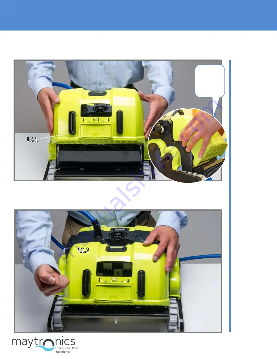
. Assembling the Cartridge Door 


Step 10.1 

Place the 
cartridge door on 
the casing 


Place the top 
side first, on 
both sides of the 
robot. 


Step 10.2 

Press strongly on 
the bottom of 
the door to fit 
the clips into 
place. 


Tip:


Place the 
top side 
first. 


Содержание BIO

Страница 1: ...iving System 3 4 Assembling the Side Panels 5 5 Assembling the Floating Cable 6 6 Positioning the Floats 7 7 Positioning the Brush Covers 8 8 Assembling the Outer Casing 8 9 Assembling the Impeller Cover 9 01 Assembling the Cartridge Door 10 11 Assembling the Handle 11 12 Assembling the Suction Inlet Plug 12 13 Assembling the Brushes 13 ...

Страница 2: ...BIO Assembly Instructions Page 2 of 14 1 Assembling the Diaphragms 2 Assembling the Motor Unit Step 1 1 Insert two diaphragms Step 2 1 There is only one way to place the motor unit in the frame ...

Страница 3: ...BIO Assembly Instructions Page 3 of 14 3 Assembling the Driving System Step 2 2 Secure the motor unit to the frame with 4X KA50X20 screws Step 3 1 Place 4 guide wheels on both sides of the robot ...

Страница 4: ...exagon adaptors into the pulley Step 3 3 Put the pulley and the Active Brush gear in their places on both sides of the robot Step 3 4 Place the track in its place as shown on both sides of the robot Step 3 5 Place the side floats on both sides of the robot ...

Страница 5: ... 5 of 14 4 Assembling the Side Panels Step 4 1 Put the side panels into place on both sides of the robot Step 4 2 Secure the side panels in place with 4 KA50X20 screws on both sides of the robot Note Make sure the clips are in place ...

Страница 6: ...able Step 5 1 Connect the cable s retrofit to motor unit mind the slot shape and press it firmly Step 5 2 Press the seal firmly to the terminal Step 5 3 Tighten the nut properly by hand Note There is only one way for the connector to connect to the motor unit terminal ...

Страница 7: ... 7 of 14 6 Positioning the Floats Step 5 4 Position the floating cable on the motor unit and secure the cable holders with 4 50X12 screws Step 5 5 The cable position on the motor unit Step 6 1 Place the two floats on the motor unit ...

Страница 8: ...embling the Outer Casing Step 7 1 Position the 2 brush safety covers on both sides of the robot Step 7 1 Position the 2 brush safety covers on both sides of the robot Step 8 1 Place the outer casing on the frame Step 8 2 Secure the outer casing to the frame with 4 50X20 screws ...

Страница 9: ...mbling the Impeller Cover Step 9 1 Place the cable support in its place on the outer casing before closing the impeller cover Step 9 2 Position the impeller cover diagonally on the outer casing Step 9 3 Secure the impeller cover with a 50X12 screw ...

Страница 10: ...01 Assembling the Cartridge Door Step 10 1 Place the cartridge door on the casing Place the top side first on both sides of the robot Step 10 2 Press strongly on the bottom of the door to fit the clips into place Tip Place the top side first ...

Страница 11: ...BIO Assembly Instructions Page 11 of 14 11 Assembling the Handle Step 11 1 Position the handle Step 11 2 Secure the handle in place with 2 50X20 screws Note The handle s position ...

Страница 12: ...BIO Assembly Instructions Page 12 of 14 12 Assembling the Suction Inlet Plug Step 12 1 Place the inlet on the side of the hose connection Step 12 2 Assemble the inlet Note The hose connection side ...

Страница 13: ...Assembly Instructions Page 13 of 14 13 Assembling the Brushes Step 13 1 Place the Active Brush in its place Step 13 2 Secure the Active Brush in place with 4 50X20 screws Step 13 3 Place one brush in place ...

Страница 14: ...BIO Assembly Instructions Page 14 of 14 Step 13 4 Place the second brush in its place by pulling it strongly against you Tip Using a screwdriver makes it easier to insert the brush in place ...

Страница 15: ...rtridge Door 3 3 Dismantling the Impeller Cover 4 4 Dismantling the Outer Casing 5 5 Dismantling the Cable 6 6 Dismantling the Side Panels 7 7 Dismantling the Driving System 8 8 Dismantling the Motor Unit 9 9 Dismantling the Suction Inlet Plug 10 10 Dismantling the Brushes 10 11 Dismantling the Diaphragms 11 ...

Страница 16: ...BIO Disassembly Instructions Page 2 of 11 1 Dismantling the Handle Step 1 1 Unscrew the 2 screws holding the handle in place Step 1 2 Take the handle off ...

Страница 17: ...ly Instructions Page 3 of 11 2 Dismantling the Cartridge Door Step 2 1 Dismantle the cartridge door using a flat screwdriver as shown in the picture Step 2 2 Remove the cartridge doors from both sides of the Dolphin ...

Страница 18: ...structions Page 4 of 11 3 Dismantling the Impeller Cover Step 2 3 Remove the suction sleeve Step 3 1 Unscrew the screw holding the impeller cover in place Step 3 2 Lift the impeller cover up from one side and take it off ...

Страница 19: ...y Instructions Page 5 of 11 4 Dismantling the Outer Casing Step 4 1 Remove the black grommet Step 4 2 Unscrew the 4 screws holding the outer casing in place Step 4 3 Hold the outer casing on both sides and pull it up ...

Страница 20: ...tructions Page 6 of 11 5 Dismantling the Cable Step 5 1 Remove 2 floats from the motor unit Step 5 2 Unscrew the 4 screws securing the cable holder Step 5 3 Unscrew the cable from the motor unit Step 5 4 Unplug the cable ...

Страница 21: ...BIO Disassembly Instructions Page 7 of 11 6 Dismantling the Side Panels Step 6 1 Unscrew the 4 screws holding each panel in place Step 6 2 Pull the side panels off ...

Страница 22: ...iving System Step 7 1 Remove the pulley together with the track from both sides of the robot Step 7 2 Remove the guide wheels Step 7 3 Remove the Active Brush s driving wheel from both sides of the robot Step 7 4 Remove the side floats from both sides of the robot ...

Страница 23: ...BIO Disassembly Instructions Page 9 of 11 8 Dismantling the Motor Unit Step 8 1 Unscrew the 4 screws securing the motor unit to the frame Step 8 2 Remove the motor unit ...

Страница 24: ... Dismantling the Suction Inlet Plug 10 Dismantling the Brushes Step 9 1 Dismantle the inlet using a small and flat screwdriver Step 9 2 Remove the inlet Step 10 1 Remove the brushes Tip Using a flat screwdriver makes it easier to remove the brush ...

Страница 25: ...BIO Disassembly Instructions Page 11 of 11 11 Dismantling the Diaphragms Step 10 2 Open the 4 screws holding the active brush in place Step 10 3 Remove the Active Brush Step 11 1 Remove the 2 diaphragms ...

Отзывы: