XCite™ OEM RF Module – Product Manual v1.1
Serial Data
Data enters the MaxStream OEM RF Module through the DI Pin (pin 4) as an asynchronous serial
signal. The signal should idle high when no data is being transmitted.
The UART performs tasks (such as timing and parity checking) needed for communication. Serial
communication consists of two UARTs which must be configured with compatible parameters
(Baud rate, parity, start bits, stop bits, data bits) to have successful communication. Each data
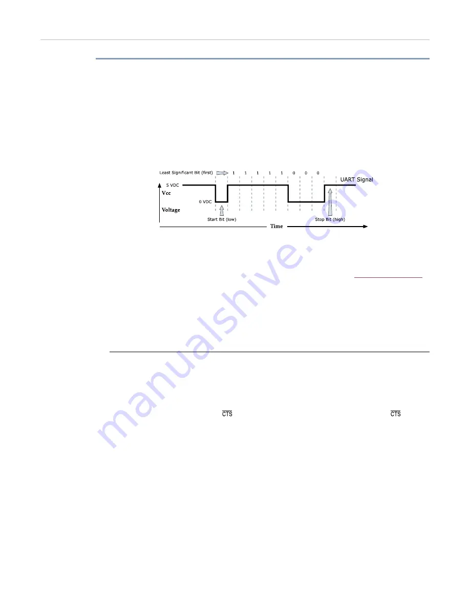
packet consists of a start bit (low), 8 data bits (least significant bit first) and a stop bit (high).
The following figure illustrates the serial bit pattern of data passing through the module.
Figure 8.
Serial (UART) data packet 0x1F (decimal “31”) as transmitted through the XCite Module
Data Format is 8-N-1 (8 bits - No Parity - 1 Stop Bit)
In the example above, the MaxStream Module transfer 8 bits over-the-air [Selectable using BI
(Number of Bits) Parameter]. Start and stop bits of the UART signal are not transmitted over-the-
air, but are regenerated by the receiving module.
The MaxStream OEM RF Modules support the following data formats [See
]:
•
8-none-1, 7-any-1
•
8-even-1
•
8-odd-1
•
8-mark-1, 8-none-2
•
8-space-1
DI (Data In) Buffer
Once serial data has entered the 9XCite Module through the Data In (DI) Pin, the data is stored
in the DI Buffer until it can be transmitted.
Once the first byte of data enters the DI Buffer, the module begins to initialize the RF channel
(unless RF data is being received). In the case where the module is receiving RF data, the serial
(UART) data is stored in the DI Buffer. When the DI Buffer has only 17 bytes of memory left, the
XCite Module de-asserts (high)
to signal to the host device to stop sending data.
re-
asserts once the DI Buffer has at least 35 bytes available in memory. Once in the DI Buffer, the
data is packetized for transmission. [Packet structures are broken down below.]
© 2004 MaxStream, Inc., Confidential and Proprietary
9


