MAX32600 User’s Guide
LCD Controller
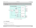
13.3 LCD Configuration
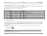
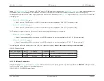
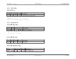
Writing 1 to
requests LCD COM mode for COM[3:0] (all four simultaneously).
is read-only acknowledgement
from hardware; read of 1 acknowledges LCD COM mode is selected for COM[3:0]. Note that the request may be denied based on port function priority.
I/O management segment requests write to single segment pins and must be a redundancy of the
segment request(s). These are accessed with the
following registers:
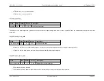
•
–
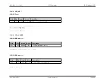
Write 1 requests LCD SEG mode for the GPIO selected in the
n
position (applicable to P3.0 – P6.7 [32 segments total])
•
–
Write 1 requests LCD SEG mode for the GPIO selected in the
n
position (applicable to P7.0 – P7.7 [8 segments total])
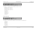
The I/O management segment requests also have associated read-only acknowledgements from hardware:
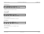
•
.io_ack_n
–
Read of 1 acknowledges SEG mode selected for the GPIO selected in the
n
position (applicable to P3.0 – P6.7 [32 segments total])
•
.io_ack_n
–
Read of 1 acknowledges SEG mode selected for the GPIO selected in the
n
position (applicable to P7.0 – P7.7 [8 segments total])
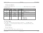
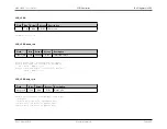
The following table outlines the bit addresses for the LCD Port Configuration registers.
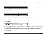
Writes to this register can only occur when OPM=0
.
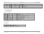
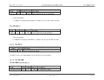
LCD_LPCF Register Details
LCD_LPCF Register
Bit
Operation
Read/Write
Details
19:0
Segment Pin Pair Enable
R/W
0 = reset; 1 = enables selected segment pin pairs
31:20
Reserved
RO
always write 0 value
13.3.6
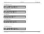
LCD Memory Configuration
LCD glass mapping to
and
values are dependent on LCD glass type and its pin interconnection to the
MAX32600
LCD segment pins.
Further information can be found in the relevant application note.
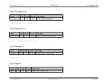
LCD_LCDATA / LCD_LCADDR Register Details
Rev.1.3 April 2015
Maxim Integrated
Page 641
Содержание MAX32600
Страница 1: ...MAX32600 User s Guide April 2015...

