


MAX32600 User’s Guide
System Configuration and Management
4
System Configuration and Management
4.1
Power Ecosystem and Operating Modes
4.1.1
Power Ecosystem
The
MAX32600
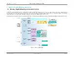
has multiple operating modes with many user configurable options offering significant flexibility in total power consumption. These options are stored
in the data retention power domain registers and are continuously powered across all modes of operation. The registers dictate which analog and digital peripherals
are intended to remain enabled during low power modes. Likewise, there are dedicated system registers that dictate the configuration of features during run modes.
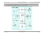
The
MAX32600
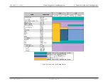
supports four power modes,
; and
. The
shows a state diagram of these
power modes.
The low power modes, LP0: STOP and LP1: STANDBY, are under the control of the Power Sequencer while LP2: PMU is controlled by the
, and the LP3: RUN
mode is controlled by the ARM core.
The V
RTC
power pad (powered by battery or super cap) ensures that this domain is always on during battery change or other loss-of-power events on the main V
DD
supply.
When a wakeup event is detected, the
MAX32600
exits the low power mode (LP0: STOP or LP1: STANDBY) and always enters LP3: RUN where firmware takes
over control of the system and power states.
Rev.1.3 April 2015
Maxim Integrated
Page 29
Содержание MAX32600
Страница 1: ...MAX32600 User s Guide April 2015...


