


MAX32600 User’s Guide
Analog Front End
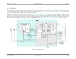
8.3 ADC
8.3.4.2
Reference Voltage Configuration
The
MAX32600
supports internal or external ADC reference voltage options. The
register selects the reference source (REFADC). Setting the
register field to 0 uses internal bandgap; setting the register field to 1 selects external reference (REFADJ).
It is required to power up the internal reference by setting
register field to 1. If using an external reference, this field must be set to 0 to
allow selection of an external reference voltage.
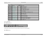
If
register is set to 1, the adjustable external ADC reference voltage must be defined by selecting the desired
bit field
setting.
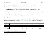
ADC reference voltage output
00b
1.024V
01b
1.5V
10b
2.048V
11b
2.5V
8.3.4.3
Input Modes
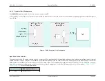
The ADC allows for both single-ended and differential input measurement modes. Internally, all ADC conversions are differential at the hardware level; the single-
ended/differential mode select determines which of the external analog input signals are used as part of the analog-to-digital conversion process.
When single-ended mode is used, the negative input to the ADC is internally grounded to V
AGND
. This is to minimize error against the reference ground. The input
mux setting for the ADC determines which signal will be connected to the ADC positive input port.
In differential mode, the ADC input mux setting controls two signal connections to the ADC positive and negative inputs. If the negative input signal pin is then
grounded, this setup becomes identical to the single-ended mode configuration.
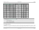
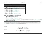
Selection of single-ended or differential input modes is shown in
8.3.4.3.1
Signal Conditioning
The
MAX32600
ADC features two signal conditioning modes: bipolar and unipolar mode. Bipolar mode must be used if the negative input could exceed the positive
input. Unipolar mode can be used if the positive input will always be greater than the negative input. When using bipolar mode, it is optimal to enable differential input
mode; using bipolar mode with single-ended input mode degrades signal resolution. In most cases, unipolar mode will be used in tandem with single-ended input
mode.
The register field
is used to select either unipolar or bipolar operation. Setting this field to 0, the default state, indicates unipolar mode; setting it
to 1 indicates bipolar operation.
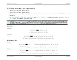
When using bipolar mode, the input range must also be configured using the register field
. A value of 0, default state, indicates a range of -V
REF
/2
Rev.1.3 April 2015
Maxim Integrated
Page 409
Содержание MAX32600
Страница 1: ...MAX32600 User s Guide April 2015...


