3-1
OPERATION
www.maxcessintl.com
Fife GMA-BL
MI 2-264 1 B
System setup
1.
C24 VDC Power to the GMA-BL Actuator Controller power cable and connect the
operator interface to the GMA-BL Actuator Controller. Refer to GMA-BL Actuator
Controller Installation and Service Manual, Figure Sheet 1-916, which is supplied with
each system.
2.
Apply the proper power to the system.
3.
Verify the system is in Manual Mode by pressing the MANUAL button on the Control
Panel.
4.
Switch the system to Servo Center Mode by pressing the SERVO-CENTER button.
5.
Thread the web/strip to be used, through the system and pull proper tension, if possible.
6.
Switch the system to Manual Mode by pressing the MANUAL button.
7.
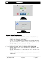
Perform “Sensor Calibration” on the sensor(s) that will provide position feedback for the
web/strip. If two sensors are being used, they must be calibrated independently. Refer to
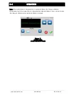
Figure 3 and Figure 4, shown on the following page.
1)
Press the SETUP button to enter the Setup menus.
2)
Press the SENSOR SETUP icon to enter the Sensor Calibration menu.
3)
Select the desired sensor by pressing the SENSOR SELECTION button.
4)
Press the ‘Start Calibration’ button to begin the calibration.
5)
The Jog buttons at the bottom of the screen may be used to move the web
material in and out of the sensor as needed during calibration.
6)
Follow the instructions displayed on the Control Panel.
7)
Be sure to use the web to be guided to calibrate the sensor(s).
8)
Repeat this procedure for each sensor, if two sensors are to be used.
9)
Once this procedure has been completed, Press the ACCEPT (√) to save the
changes.
10)
Press the BACK or HOME button to return to the Operator Level screen.
Once this procedure has been performed once for each sensor, it does not need to be
repeated, unless the web/strip opacity has changed.
Figure 3.
CONTROL PANEL
LEVEL 1 SETUP SCREEN
Содержание Fife GMA-BL
Страница 1: ...Fife GMA BL Actuator Controller Quick Start Manual EN MI 2 264 1 B...
Страница 2: ......
Страница 15: ......


