


11
1.4 Electrical Requirements
For your safety and treadmill performance, the ground on this circuit must be non-looped. Please
refer to NEC article 210-21 and 210-23. Your Treadmill is provided with a power cord with a
plug and requires a dedicated line according to the electric configurations listed in the chart
below. Any alteration of this power cord could void all warranties of this product.
1.5 grounding instructions
The treadmill must be grounded. If it should malfunction or breakdown, grounding provides a path
of least resistance for electric current to reduce the risk of electric shock. The treadmill is equipped
with a cord having an equipment- grounding conductor and a grounding plug. The plug must be
plugged into an appropriate outlet that is properly installed and grounded in accordance with all
local codes and ordinances. If the user does not follow these grounding Instructions, the user could
void the Matrix limited warranty.
danger:
Improper connection of the equipment-grounding conductor can result in a risk of electric shock.
Check with a qualified electrician or serviceman if the user is in doubt as to whether the product is
properly grounded. Do not modify the plug provided with the product if it will not fit the outlet;
have a proper outlet installed by a qualified technician.
Содержание MX-T3x
Страница 1: ...1 MX T3x TM94E AC SYSTEM SERVICE MANUAL...
Страница 4: ...4 SERIAL NUMBER LOCATION SECTION 1...
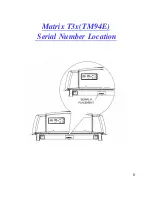
Страница 5: ...5 Matrix T3x TM94E Serial Number Location...
Страница 6: ...6 MOVING THE UNIT SECTION 2...
Страница 8: ...8 IMPORTANT SAFETY I N S T R U C T I O N S SECTION 3...
Страница 12: ...12 PREVENTATIVE MAINTENANCE SECTION 4...
Страница 19: ...19 SECTION 5 MANAGER MODE...
Страница 23: ...23 SECTION 6 TROUBLE SHOOTINGS...
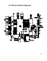
Страница 24: ...24 6 1 Electrical block diagram...
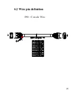
Страница 25: ...25 6 2 Wire pin definition P01 Console Wire...
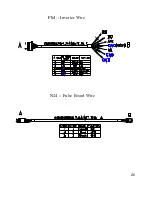
Страница 26: ...26 P04 Inverter Wire N24 Pulse Board Wire...
Страница 27: ...27 P11 CTRL Overlay Wire Left P12 CTRL Overlay Wire Right...
Страница 35: ...35...
Страница 39: ...39 SECTION 7 PARTS REPLACEMENT...
Страница 42: ...42 Figure D Figure E...
Страница 53: ...53 Figure D Figure E Figure F Figure G...
Страница 57: ...57 Install the MSP430 Tools Computer...
Страница 58: ...58 Press the Load Image Installation software to MSP430 Tools...
Страница 59: ...59 Installing the MSP430 cable to console MSP430...
Страница 61: ...61 SECTION 8 UPGRADES...