29
3.5.2.
Modem HW v5.1
is a superior version of the Modem HW v4.9.
Modem HW v5.1 looks almost the same as Modem HW v4.9. To
distinguish it, check white sticker on the bottom
Modem HW v5.1 and Modem HW v4.9 brief comparison:
-
Modem HW v5.1 has more memory
-
Modem HW v5.1 has higher radio range
-
Modem HW v5.1 more sensitive
-
Modem HW v5.1 has TELEC T-108 Japan certification
-
All new features come to the new Modem HW v5.1
-
-
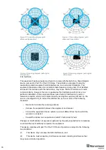
FCC NOTICE:
This equipment has been tested and found to comply with the limits for a Class B digital
device, pursuant to Part 15 of the FCC Rules. These limits are designed to provide
reasonable protection against harmful interference in a residential installation. This
equipment generates, uses and can radiate radio frequency energy and, if not installed
and used in accordance with the instructions, may cause harmful interference to radio
communications. However, there is no guarantee that interference will not occur in a
particular installation. If this equipment does cause harmful interference to radio or
television reception, which can be determined by turning the equipment off and on, the
user is encouraged to try to correct the interference by one or more of the following
measures:
Reorient or relocate the receiving antenna
Increase the separation between the equipment and receiver
Connect the equipment into an outlet on a circuit different from that to which the receiver
is connected
Consult the dealer or an experienced radio/TV technician for help
Changes or mo
difications not expressly approved by the party responsible for compliance
could void the user's authority to operate the equipment.
This device complies with part 15 of the FCC Rules. Operation is subject to the following
two conditions:
(1)
This device may not cause harmful interference, and
(2)
This device must accept any interference received, including interference that
may cause undesired operation.
The equipment should be installed and operated with minimum distance 20cm between
the radiator & your body.
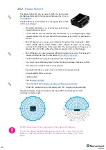
Fig.1: Modem HW v5.1
Fig.2: Bottom sticker
Содержание IA-04-2D-Badge
Страница 1: ...Marvelmind Indoor Navigation System Operating manual v2022_08_24 www marvelmind com ...
Страница 18: ...18 Here is a tutorial video about architectures Help Inverse Architectures IA vs Non Inverse Architectures NIA ...
Страница 21: ...21 Beacon Mini TX Beacon Industrial RX Beacon Industrial TX Metal ...
Страница 22: ...22 Industrial Super Beacon Plastic ...
Страница 34: ...34 The equipment should be installed and operated with minimum distance 20cm between the radiator your body ...
Страница 36: ...36 Figure 2 Super Beacon with two External Microphones connected Figure 3 Super Beacon with Omni ...
Страница 39: ...39 Figure 7 One External Microphone connection Figure 8 Two External Microphone connection ...
Страница 44: ...44 Figure 3 One external microphone soldering Figure 4 Two external microphones soldering ...
Страница 46: ...46 Figure 7 Two External Microphones final view Figure 8 Two External Microphones final view ...
Страница 118: ...118 6 6 28 The system is now fully operational ...
Страница 132: ...132 7 9 1 2 Advanced settings TBD TBD TBD TBD TBD TBD If modem lost connection it restarts by itself TBD TBD TBD TBD ...
Страница 157: ...157 Example 4 No handover zone 10 11 12 14 Service zones not cross NO HANDOVER ZONE CREATED NO HANDOVER BETWEEN SUBMAPS ...
Страница 163: ...163 Move submaps as you wish Use CTRL and mouse roll to rotate Submap Awake mobile beacons It will apeare in a map ...
Страница 169: ...169 To turn on one of the mic in a specific pair press on a specific box below RX2 RX4 with CTRL ...
Страница 180: ...180 Floor 5 is enabled Floor 4 is enabled ...
Страница 190: ...190 Z X ...
Страница 207: ...207 Choose color and press OK Color applied Now background matches floorplan ...
Страница 209: ...209 Choose any color which suits you and press OK Now the hedgehog and its tracking path will be colored ...
Страница 214: ...214 9 24 IMU axis positioning Super Beacon IMU axis positions HW v4 9 IMU axis positions ...
Страница 215: ...215 Mini TX IMU axis positions Mini RX beacon IMU axis positions ...
Страница 219: ...219 Real time player turned on ...
Страница 222: ...222 10 1 Super beacon external interface pinout top view 4x4 pinout for Super Beacon 4x4 pinout for Super Beacon 2 ...
Страница 223: ...223 10 2 Beacon HW v4 9 external interface 4x4 pinout top view ...
Страница 224: ...224 10 3 Modem HW v4 9 external interface pinout top view ...
Страница 232: ...232 If everything done correctly Own IP address will change Static IP settings completed ...
Страница 238: ...238 How to change modes Choose hedge Go to Ultrasound TDMA mode Left Click to change ...


