


2
NBT40 SERVICE MANUAL
HYDRAULIC SYSTEM
National Crane
Published 8-01-2017 Control # 287-11
2-17
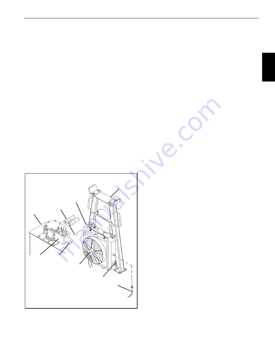
Hydraulic Oil Cooler
A hydraulic oil cooler (4, Figure 2-11) is located on the boom
rest (7). The oil cooler return circuit (3) is in parallel with the
reservoir return circuit (6). The oil cooler inlet (2) and return/
out circuits run through the by-pass block (5) on top of the
reservoir (1). A 206 kPa (30 psi) check valve in the by-pass
block (5) regulates flow through the oil cooler (9). When the
hydraulic oil is cold, most of the return oil goes directly to the
tank. As the oil warms up and becomes thinner, more oil
goes through the cooler.
NOTE:
A temperature sensor located in swivel port (4B)
monitors the temperature of the hydraulic oil and
illuminates a light on the crane cab console when
the temperature reaches 96° C (205° F).
The oil cooler fan (9) is controlled by a relay in VEC module.
To access the relay, remove the assess panel on the side of
the housing. A temperature switch located in the cooling core
energizes the fan relay when the oil temperature reaches 49
°C (120°F), the switch is connected to the oil cooler harness
(8) at the temp sensor port.
NOTE:
If the temperature sensor in the cooling core fails,
the fan runs (9) continuously even when the crane
ignition is off.
Oil Cooler Service & Maintenance
The heat exchanger must be kept clean to allow for efficient
operation of the cooler system. Frequent washing of the heat
exchanger core eliminates oil film, road dirt, and other
foreign object buildup on the heat exchanger fins which
reduces cooling efficiency.
Frequent inspection and tightening of hose clamp line
connections eliminates the possibility of end connection
failure due to back pressure from cold startup.
If the cooler system fails to provide adequate performance,
reduced air or oil flow through the heat exchanger is the
probable cause. Inspect the cooling fan for proper operation.
Any obstructions to air flow needs to be corrected (cooler too
close to other truck components, foreign matter in heat
ex ch an ger fins , etc .). Al l hy dra ulic line s sh ould be
periodically checked for obstructions, hose kinks or other
flow restrictions.
Hydraulic Valves
Inspection
Inspect the control valve for visible damage, binding spools,
and evidence of leakage. If excessive internal leakage is
suspected during operation with a spool in its center position,
it is possible that the area between the spool and working
section bore of the valve body is worn beyond serviceable
limits. If this condition exists, the spool and body must be
replaced as an assembly.
Valve Leakage
Dripping hydraulic oil indicates some type of external
leakage. The machine should be removed from service for
immediate repairs. External leaks sometimes develop at
fittings and seals. Spool seals are susceptible since they are
subject to wear. Seals may be damaged by temperatures
that are too high, or by dirt or paint accumulation on the
spool. Damaged seals must be replaced.
A component functioning at reduced efficiency may indicate
that the control valve for that component is leaking internally.
If preliminary check-out reveals that adequate volume is
being supplied to the affected valve bank, relief valves are
properly adjusted, and the component is not at fault, check
the valve for scored or worn parts. Scoring is a usually sign of
contamination (external contamination by dust or internal
contamination by debris from deteriorating components or
oxidized hydraulic oil). Scored or severely worn valve
components must be replaced.
Check valves in the control valve are designed to permit a
flow of hydraulic oil in one direction only. If a piece of dirt or
rust has worked its way into the check valve and lodges
between the poppet and seat, it will keep the valve open and
allow a return flow of hydraulic oil. Clean the valve and check
that the hydraulic system filter is still serviceable.
3
FIGURE 2-11
5
8
6
2
1
4
7
3
9
Reference Only
Содержание National Crane NBT40 Series
Страница 1: ...Service Manual National Crane NBT40 Series R e f e r e n c e O n l y ...
Страница 2: ...R e f e r e n c e O n l y ...
Страница 122: ...BOOM MAINTENANCE NBT40 SERVICE MANUAL 4 48 Published 8 01 2017 Control 287 11 THIS PAGE BLANK R e f e r e n c e O n l y ...
Страница 136: ...HOIST NBT40 SERVICE MANUAL 5 14 Published 8 01 2017 Control 287 11 THIS PAGE BLANK R e f e r e n c e O n l y ...
Страница 162: ...OUTRIGGERS NBT40 SERVICE MANUAL 7 10 Published 8 01 2017 Control 287 11 THIS PAGE BLANK R e f e r e n c e O n l y ...
Страница 214: ...CRANE INSTALLATION NBT40 SERVICE MANUAL 9 36 Published 8 01 2017 Control 287 11 7488 4 7488 6 R e f e r e n c e O n l y ...
Страница 216: ...SCHEMATICS NBT40 SERVICE MANUAL 10 2 THIS PAGE BLANK R e f e r e n c e O n l y ...
Страница 218: ...NBT40 SERVICE MANUAL APL 2 THIS PAGE BLANK R e f e r e n c e O n l y ...
Страница 219: ...R e f e r e n c e O n l y ...
Страница 220: ...R e f e r e n c e O n l y ...


