PRINTED IN U.S.A.
69
50960025/CP0514
NOTE:
Before replacing the filter element(s),
push the reset button on the indicator. Start the
engine and run at full throttle. If the indicator does
not turn red, do not replace the element(s).
The outer element should be replaced only when the
restriction indicator turns red. The inner element
should be replaced every third time the outer element
is replaced, unless the outer element is damaged or the
inner element is visibly dirty. Along with a daily check
of the restriction indicator, check that the air cleaner
intake hose and clamps, and the mounting bracket
hardware are properly secure.
Unlatch the three latches on the air cleaner and remove
the end cap assembly. Clean out any dirt built up in the
end cap assembly.
Primary Element
1.
Carefully pull the primary (outer) element out of
the housing. Never remove the secondary (inner)
element unless it is to be replaced.
2.
Clean out any dirt built up in the housing. Leave
the secondary element installed during this step to
prevent debris from entering the engine intake
manifold.
3.
Use a trouble light inside the primary element to
inspect for bad spots, pinholes and ruptures.
Replace the primary element if any damage is
noted. The primary element must be replaced if it
is oil- or soot-laden.
NOTE:
Cleaning the primary element is not rec-
ommend.
Secondary Element
NOTE:
Replace the secondary element only if it is
visibly dirty or if the primary element has been
replaced three times.
Before removing the secondary element from the hous-
ing, clean out any dirt built up in the housing. Leave
the secondary element installed during this step to pre-
vent debris from entering the engine intake manifold.
Remove the secondary element.
Reinstallation
1.
Check the inside of the housing for any damage
that may interfere with the elements.
2.
Be sure that the element sealing surfaces are
clean.
3.
Insert the element(s), making sure that they are
seated properly.
4.
Secure the end cap to the housing with the three
latches.
5.
Check the hose connections and make sure they
are all clamped and tightened properly.
6.
Reset the restriction indicator by pressing the
reset button.
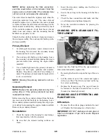
CHANGING OPEN CRANKCASE FIL-
TER ELEMENT
Located near the final fuel filter, the open crankcase
filter element should be replaced by:
1.
Removing the thread-on cap on the top of the can-
ister.
2.
Lift the element out of the canister and replace
with a new filter. The filter is notched on the top
for correct positioning.
3.
Replace the thread-on cap. The cap will need to
be indexed to the filter element before it can be
threaded on. Hand tighten only.
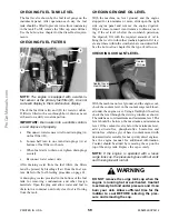
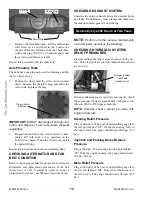
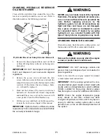
CHANGING AXLE DIFFERENTIAL AND
PLANETARY OIL
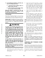
Differentials
1.
Remove the three drain plugs and drain the used
oil. Replace the drain plugs
(see illustration).
IMPORTANT:
DO NOT discharge oil onto ground.
Catch and dispose of per local waste disposal
regulations.
Open
Crankcase Vent
Содержание MT10044XT
Страница 12: ...50960025 CP0514 8 PRINTED IN U S A INTENTIONALLY BLANK To be removed as Dealer s file copy ProCarManuals com...
Страница 25: ...PRINTED IN U S A 21 50960025 CP0514 SAFETY 808034 808035 808033 808032 808036 808031 51200535 ProCarManuals com...
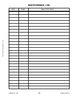
Страница 85: ...PRINTED IN U S A 81 50960025 CP0514 Date Hours Service Procedure MAINTENANCE LOG ProCarManuals com...
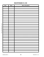
Страница 86: ...50960025 CP0514 82 PRINTED IN U S A Date Hours Service Procedure MAINTENANCE LOG ProCarManuals com...
Страница 87: ...PRINTED IN U S A 83 50960025 CP0514 Date Hours Service Procedure MAINTENANCE LOG ProCarManuals com...
Страница 91: ...PRINTED IN U S A 87 50960025 CP0913 Hydraulic Schematic for Two Joystick Control without PWP ProCarManuals com...
Страница 92: ...50960025 CP0913 88 PRINTED IN U S A Hydraulic Schematic for Two Joystick Control with PWP ProCarManuals com...
Страница 93: ...PRINTED IN U S A 89 50960025 CP0913 Hydraulic Schematic for Tri Function Joystick without PWP ProCarManuals com...
Страница 94: ...50960025 CP0913 90 PRINTED IN U S A Hydraulic Schematic for Tri Function Joystick with PWP ProCarManuals com...
Страница 95: ...PRINTED IN U S A 91 50960025 CP0913 Electrical Schematic with Radio Remote ProCarManuals com...
Страница 96: ...50960025 CP0913 92 PRINTED IN U S A Electrical Schematic without Radio Remote ProCarManuals com...
Страница 97: ...PRINTED IN U S A 93 50960025 CP0514 INTENTIONALLY BLANK ProCarManuals com...
Страница 108: ...50960025 CP0514 104 PRINTED IN U S A Load Zone Charts MT10055XT Work Platform Decal 50380043 ProCarManuals com...
Страница 114: ...50960025CP0514 2014 Manitou Americas Inc PRINTED IN U S A All Rights Reserved ProCarManuals com...


