background image

50960025/CP0514

26

PRINTED IN U.S.A.

A2 Bottom position:

In this position the auto exhaust

filter cleaning is disabled.

A3 Top position:

In this position the operator initi-

ates a manual exhaust filter cleaning operation.
This process allows the system to clean the
exhaust filter when the operator previously dis-
abled exhaust filter cleaning by pressing the bot-
tom of the switch. The top of the switch will need
to be pressed for at least three seconds to activate.
The indicator in the switch will illuminate when
activated and be off when the exhaust filter clean-
ing is complete.

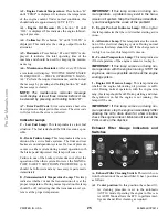
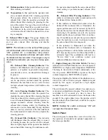
B - Exhaust Filter Gauge:

This gauge displays the

four indicators you will see through the operator initi-
ated or auto exhaust filter cleaning and disable
processes.

NOTE:

The indicators in the exhaust filter gauge

will all illuminate when the keyswitch is put in the
“ON” position for a momentary lamp check.
During normal operation all lamps will never all be
illuminated at the same time. This image is only to
illustrate the indicators you may see during oper-
ation.

B1 - Exhaust Filter Cleaning Indicator:

This

indicator will illuminate when exhaust gas tem-
perature is at optimal regeneration temperature,
elevated idle is active, or exhaust filter cleaning is
in process.

When this indicator is illuminated, the machine
can be operated as normal unless the operator
determines the machine is not in a safe location
for high exhaust temperatures and disables auto
cleaning.

B2 - Auto Cleaning Disabled Indicator:

This

indicator  will illuminate when the operator has
disabled the auto exhaust filter cleaning function
from the exhaust filter cleaning switch (A). This
icon will remain illuminated until the operator re-
engages automatic exhaust cleaning from the
exhaust filter cleaning switch (A). Disabling the
auto mode is not recommended for any situation
unless it is safety related or if the fuel tank lacks
the recommended 1/4 tank of fuel to complete the
cleaning process.

B3 - Exhaust Filter Indicator:

This indicator

will illuminate when the exhaust filter is in need
of cleaning because the soot level of the exhaust
filter is slightly high and the operator has disabled
auto exhaust filter cleaning. If conditions are safe,

the operator should enable the auto exhaust filter
clean setting or perform manual exhaust filter
cleaning.

B4 - Exhaust Filter Warning Indicator:

This

amber or red indicator works in combination with
the Exhaust Filter Indicator (B3).

If this indicator is illuminated amber when the
Exhaust Filter Indicator (B3) is illuminated, the
engine performance will be reduced by the ECU
because the soot level of the exhaust filter is mod-
erately high. If conditions are safe, the operator
should enable the auto exhaust filter clean func-
tion. If conditions are not safe,the operator should
move the machine to a safe location and engage
the auto exhaust filter cleaning mode.

If this indicator is illuminated red when the
Exhaust Filter Indicator (B3) is illuminated, the
engine performance will be further reduced by the
ECU because the soot level of the exhaust filter is
extremely high. This combination will lead to a
“Service Only” soot condition, contact your
authorized Manitou Americas dealer.

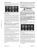
C - Engine Emergency Override Switch:

The lamp

in this switch will flash when there is a low oil pressure
WARNING or a high coolant temperature WARNING.
The lamp in the switch will light continuously at the
low oil pressure SHUTDOWN set-point or the high
coolant temperature SHUTDOWN set-point.

Pressing and holding the bottom of the shutdown over-
ride switch will override an engine shutdown signal
caused by low engine oil pressure or high engine
coolant temperature.

The switch must be pressed within 30 seconds to pre-
vent undesired shutdown of engine. The switch can be
overridden for 30 seconds at a time to move the
machine to a safe location and to lower the boom to the
ground. If the engine shuts down, the ignition switch
must be turned off and then back on before the engine
can be restarted.

NOTE:

Holding the switch continously “ON” will

not reset the 30-second timer.

Switch Panel

The switch panel contains three rows of switches for
the operation of standard and optional equipment on
the telescopic handler.

ProCarManuals.com

Содержание MT10044XT

Страница 1: ...pic Handler Operator Service Manual Catalog 50960025 Revision C MT6642XT beginning with S N 27251 MT8044XT beginning with S N 28251 MT10044XT beginning with S N 80151 MT10055XT beginning with S N 8015...

Страница 2: ...erature Fan Frame Level Left Crab Steer Lower Load 2 Wheel Steer Raise Load 4 Wheel Steer Engine Coolant Temperature Hourmeter Retract Load Volume Empty Starting Aid Injection Tilt Rearward Wiper Wash...

Страница 3: ...beginning with S N 28251 MT10044XT beginning with S N 80151 MT10055XT beginning with S N 80151 MT12042XT beginning with S N 38101 Manitou Americas Inc One Gehl Way P O Box 179 West Bend WI 53095 0179...

Страница 4: ...w safety operating and maintenance instructions could result in seri ous injury to the operator or bystanders poor operation and costly breakdowns If you have any questions on proper operation adjustm...

Страница 5: ...3 Check Lists 6 7 4 SAFETY 9 5 Indicators and Controls 23 6 Operation and Adjustments 35 7 Lubrication 53 8 Service and Storage 56 9 Decal Locations 74 10 Maintenance 79 Engine Diagnostic Trouble Cod...

Страница 6: ...n will improve operating and maintenance efficiency help to avoid breakdowns and damage and extend the machine s life A chart of standard hardware torques is located in the back of this manual A stora...

Страница 7: ...r Boom Access Rear Lights and Backup Alarm Access Quick attach System Extend Cylinder Storage Compartment Battery Access Fuel Tank Frame Leveling Cylinder Telescopic Boom Slave Cylinder Side View Mirr...

Страница 8: ...MT10055 MT12042 14 00 x 24 12 PR Inflate to 62 psi 430 kPa 14 00 x 24 16PR Rock Inflate to 70 psi 480 kPa 14 00 x 24 12 PR foam filled 13 00 x 24 Solid rubber tire double aper ture with conventional t...

Страница 9: ...Dana model 212HY Drive steer open differential full time four wheel drive internal SAHR parking brake in front axle Overall ratio 22 67 1 MT10044 MT10055 MT12042 Type Dana model 223 Front axle Drive...

Страница 10: ...all function properly q No hydraulic system leaks when under pressure q Listen for abnormal noises or vibrations if detected deter mine their cause and repair as necessary I acknowledge that the pre d...

Страница 11: ...function properly q No hydraulic system leaks when under pressure q Listen for abnormal noises or vibrations if detected deter mine their cause and repair as necessary I acknowledge that the pre deli...

Страница 12: ...50960025 CP0514 8 PRINTED IN U S A INTENTIONALLY BLANK To be removed as Dealer s file copy ProCarManuals com...

Страница 13: ...e not fluent in reading English It is the responsibility of the operator to read and understand the Operator s Manual and other informa tion provided and use the correct operating procedure Machines s...

Страница 14: ...me illustrations used in this manual may show doors guards and shields open or removed for illustration purposes ONLY BE SURE that all doors guards and shields are in their proper oper ating positions...

Страница 15: ...o an excavation or ditch BE SURE that the surrounding ground has adequate strength to support the weight of the machine and the load it is carrying ALWAYS wear appropriate personal protective equipmen...

Страница 16: ...andler equipped with a jib or truss boom with a hook with or without a winch or a hook assembly attached to the forks Note This regulation is in addition to the OSHA regulation that requires specific...

Страница 17: ...ng proce dure detailed in the Service and Storage chapter NEVER use your hands to search for hydraulic fluid leaks Use a piece of paper or cardboard Escaping fluid under pressure can be invisible and...

Страница 18: ...apacities Modifications and additions that affect capacity or safe operation must never be performed with out the manufacturer s prior written approval Where such authorization is granted any applica...

Страница 19: ...al lift 9 Be sure the platform is horizontal before lifting 10 Be sure that the forklift has a firm footing SAFETY 11 Be sure that any required restraining means rail ings chains harnesses etc are in...

Страница 20: ...als as shown in the diagram at the bottom of the battery holder 5 Replace the cover and install the screws to secure the cover in place Work Platform Design Requirements Per ANSI ITSDF B56 6 2005 Sec...

Страница 21: ...nd lanyard A guardrail or similar structure shall have a nominal height to the platform floor of 42 inch es 1066 mm around its upper periphery and include a midrail It may be hinged removable or of ch...

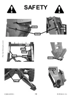
Страница 22: ...50960025 CP0514 18 PRINTED IN U S A SAFETY 808033 808030 808026 808027 808029 808037 808031 808033 808038 50380987 ProCarManuals com...

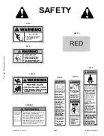
Страница 23: ...PRINTED IN U S A 19 50960025 CP0514 SAFETY RED 808038 808031 808033 808037 808029 808027 808030 50380987 ProCarManuals com...

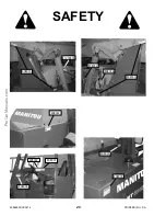
Страница 24: ...50960025 CP0514 20 PRINTED IN U S A SAFETY 808033 51200535 808033 808036 808034 808033 808035 808033 808035 808031 808032 ProCarManuals com...

Страница 25: ...PRINTED IN U S A 21 50960025 CP0514 SAFETY 808034 808035 808033 808032 808036 808031 51200535 ProCarManuals com...

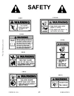
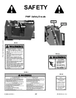
Страница 26: ...50960025 CP0514 22 PRINTED IN U S A PWP Safety Decals SAFETY 808039 808040 808041 808040 808039 808042 808042 808039 808041 ProCarManuals com...

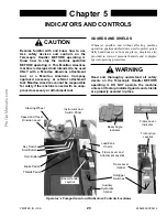
Страница 27: ...t Know how to stop the machine operation BEFORE operating it This Manitou Americas machine is designed and intended to be used ONLY with a Manitou Americas attachment tool or a Manitou Americas Compan...

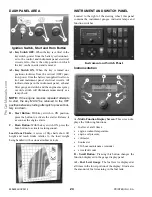
Страница 28: ...o this is the only position in which the key can be inserted and removed A2 Key Switch ON When the key is turned one position clockwise from the vertical OFF posi tion power from the battery is suppli...

Страница 29: ...E Transmission Oil Temperature Lamp This lamp indicates whether or not the transmission oil is at the proper temperature During normal operation this lamp should be off indicating that the transmissio...

Страница 30: ...when the exhaust filter is in need of cleaning because the soot level of the exhaust filter is slightly high and the operator has disabled auto exhaust filter cleaning If conditions are safe the oper...

Страница 31: ...ic con trol functions during load placement C Personnel Work Platform This is a red switch used to activate the Personnel Work Platform PWP System When activated an amber lamp in the switch will be on...

Страница 32: ...ater Fan Speed This knob is located below the tempera ture control knob Rotating the knob clockwise will increase the fan speed for increased air circulation Heater A C Controls Fan Speed This is the...

Страница 33: ...on the pedal decreases engine speed Service Brake Pedal Pressing this pedal activates inboard hydraulic wet disc type brakes on all four wheels Separate front and rear brake systems allow bringing the...

Страница 34: ...boom raised or extended Only level the frame while stopped and with the boom fully retracted and the attachment raised just enough to clear the ground Frame Level and Attachment Joystick Boom Control...

Страница 35: ...ves located on the top rear of the hydraulic reservoir under the access cover on the front hood section If the machine is equipped with auxiliary hydraulics there will be two pilot pressure apply valv...

Страница 36: ...und surface Boom Angle Indicator Mounted on the left side of the outer boom the movement of a ball indicates the angle of boom elevation relative to the ground SERVICE AND SAFETY FEATURES Transmission...

Страница 37: ...ner needs service If the clear portion of the indicator is red the air cleaner should be checked for a clogged filter element Backup Alarm Located inside the rear frame cover it produces a loud warnin...

Страница 38: ...r Motor RELAYS A 20 40 AMP change over relay Ignition B 20 40 AMP change over relay Ignition C 20 AMP relay Front Wiper D 20 AMP relay Park Brake E 20 AMP relay Lights F 20 AMP relay Top Wiper ATTACHM...

Страница 39: ...peration If engine will idle longer that 5 minutes stop the engine Consult the Lubrication chapter for the type and grade of oil to use Refer to the Service and Storage chapter for the proper service...

Страница 40: ...toward the rear of the machine on the left side and around the back and toward the front on the right side of the machine Any needed repairs or service noted during the inspec tion must be performed b...

Страница 41: ...ylinder properly lubricated o13 Slave Cylinder Properly secured no visible dam age no evidence of leaking from the cylinder prop erly lubricated o14 Stabilizer Switch Properly secured no visible dam a...

Страница 42: ...that there are no fuel oil or engine coolant leaks and no abnormal noises or vibrations COLD STARTING PROCEDURES The engine is equipped with glow plugs for starting the engine in temperatures down to...

Страница 43: ...to the opposite direction Shifting to the next higher gear may be done at any engine speed while the machine is in motion DO NOT overspeed the engine when down shifting Allow the machine to slow down...

Страница 44: ...oot in the exhaust filter system 1 Utilize the Automatic AUTO Exhaust Filter Cleaning mode 2 Avoid unnecessary idling 3 Use the proper engine oil See Lubrication chap ter of this manual or the engine...

Страница 45: ...safe location and either enable the auto exhaust filter cleaning or perform a manual exhaust filter cleaning specific conditions During this process the engine speed will be controlled by the ECU The...

Страница 46: ...nt tools The Quick attach System has a quick release hookup and locking mechanism for mounting framing type or masonry type attachment tools to the boom nose Attaching Procedure To pick up the attachm...

Страница 47: ...s obstacles slippery surfaces and soft or deep mud 6 Check clearances of ramps doorways and passageways Check overhead clearances if you will travel and place loads near power or tele phone lines If t...

Страница 48: ...ravel up or down a grade or slope that exceeds 22 or 12 while loaded 3 DO NOT place or retrieve loads on a side hill with a slope or grade that exceeds 12 or 7 Regardless of terrain or position of whe...

Страница 49: ...guarded clearly and distinc tively marked or clearly visible Maintain a safe distance from the edge of ramps plat forms and other similar working surfaces Controlled lighting of adequate intensity sh...

Страница 50: ...rve when the boom extension mark number 4 on the boom is visible and stop further extension The operator knows the maximum safe extension distance with the 4000 lb load has been reached HANDLING NON S...

Страница 51: ...er than the landing point 4 Continuing the feathering technique lower the load into place 5 Free the forks from the load by alternately retract ing and raising the boom If this process is not possible...

Страница 52: ...boom enough to clear the rigging from the load before backing the telehandler away from the load Elevated Suspended Load Placement 1 Bring the telehandler as close as possible to the landing point 2 L...

Страница 53: ...Elevating Personnel This Telescopic Handler is primarily intended for use as a material handler It should only be used to elevate personnel if it is equipped with the optional PWP System when there is...

Страница 54: ...rm is to be moved To de activate the system apply and hold the service brakes on for three or more seconds and press the bot tom of the PWP System rocker switch The system is de activated when the lam...

Страница 55: ...trailer bed with NO step between the bed and the ramps 3 The incline of the ramps MUST be less than 15 degrees For a four foot high truck bed ramp length must be at least 16 feet 4 9 m long 4 Ramp wid...

Страница 56: ...ng actions as possible to discour age theft to aid in the recovery of the machine in the event it is stolen and to reduce vandalism 1 Remove keys from unattended machines 2 Attach secure and lock all...

Страница 57: ...ation CJ 4 API Service Classification for first 100 hours on new or rebuilt John Deere engines CJ 4 Capacity 15 5 quarts 14 7 L Diesel Fuel IMPORTANT Use ONLY ultra low sulfur diesel ULSD fuel with a...

Страница 58: ...7 Tilt cylinder pivot pins 2 8 Boom slide pads as required front and rear CHASSIS AREA 9 Brake pedal linkage 10 Wheel spindle pins 4 per axle 11 Stabilizer cylinder pivot pins 3 12 Axle pivot pins 2...

Страница 59: ...PRINTED IN U S A 55 50960025 CP0514 Grease Fittings Locations 3 6 7 8 8 5 14 10 12 13 11 15 2 16 4 5 1 9 ProCarManuals com...

Страница 60: ...ng cen ter for disposal DO NOT pour them onto the ground or into a drain DEALER SERVICES The following areas of internal components service replacement and operating adjustments should only be by or u...

Страница 61: ...trical components and switch connections It is located at the back of this manual and can be used as a guide for service refer ence as required OPERATOR SERVICES Some of the operator related services...

Страница 62: ...ive clothing gloves and shoes Keep feet clothing hands and hair away from moving parts Always wear safety glasses or goggles for eye protection from electric arcs from shorts flu ids under pressure an...

Страница 63: ...ground and the engine stopped for ten minutes or more slide open the right side engine panel and remove the engine dipstick Wipe it clean re insert it and remove to obtain a read ing If the oil level...

Страница 64: ...the sight gauge located on the right side of the front hood If low remove the access cover from the front hood to replenish the oil through the filler cap See the Lubrication chapter for the type of o...

Страница 65: ...and joystick control lockout logic 1 Shift transmission into F Forward and increase the engine speed slightly l The transmission should remain de clutched allowing the engine to increase speed easily...

Страница 66: ...re Remove the oil check plug See illustration below Oil should flow from the hole If low remove the oil fill plug and add oil until it flows from the check hole Replace the plug wait 10 to 15 minutes...

Страница 67: ...ure below Fuel Bleeding Procedure When the fuel filter is removed and replaced or if the engine runs out of fuel air must be bled from the sys tem Refer to the following procedure for proper bleed ing...

Страница 68: ...to 1 1 4 turn after gasket contact is made as is done with standard filters 6 Clean and re install the drain plug 7 Re fill the crankcase with new oil Follow specifi cations in the Lubrication chapter...

Страница 69: ...boom two of the chains are on the top front of the boom A third chain is accessible from inside the rear of the boom see three section boom illustration Torque the two chains on the front of the three...

Страница 70: ...ion measures 12 375 314 mm or more the chain should be replaced DO NOT repair sections of a chain Replace the complete chain Chain anchors and sheaves also require inspection for worn or broken finger...

Страница 71: ...oom starts to chatter under load grease the slide pads and wipe off the excess grease Maintain a clear ance of 1 16 between the top or side slide pads and the boom Shims can be added to achieve the pr...

Страница 72: ...htly Recheck the level with the dipstick CHANGING HYDRAULIC RETURN FILTER ELEMENT This element is a cartridge type accessible from a housing on top of the hydraulic reservoir Initial replacement is af...

Страница 73: ...ement NOTE Replace the secondary element only if it is visibly dirty or if the primary element has been replaced three times Before removing the secondary element from the hous ing clean out any dirt...

Страница 74: ...EXHAUST SYSTEM Examine the entire exhaust system for possible holes and leaks Re tighten any loose clamps and make sure the manifold outlet gasket is not leaking NOTE Perform all other service require...

Страница 75: ...ats and fill with recommended coolant IMPORTANT DO NOT discharge coolant onto ground Catch and dispose of per local waste dis posal regulations Refer to the John Deere engine manual for detailed coola...

Страница 76: ...ble clamps and cover the battery or remove the battery from the machine and store it separately 6 If the ambient temperature at any time during the storage period is expected to drop below freez ing m...

Страница 77: ...ystem switch is turned OFF Possible Cause PWP System is not activated Machine is not level Remote PWP System switch is de activated Remote PWP System switch is not plugged into the connector at the en...

Страница 78: ...remove the backing paper Then properly orient and position the decal onto the clean mounting surface After the decal is firmly applied and smoothly pressed down remove the front covering paper DECAL...

Страница 79: ...049 808049 808049 NO 2 EXTENSION MARKER 1 ea 808050 808050 808050 808050 808050 NO 3 EXTENSION MARKER 1 ea 808051 808051 808051 808051 808051 NO 4 EXTENSION MARKER 1 ea 808052 808052 808052 808052 808...

Страница 80: ...57 808057 808057 808057 05 WARNING NO RIDERS 808035 808035 808035 808035 808035 06 MANITOU LOGO SMALL 103275 103275 103275 103275 103275 07 DANGER PERSONNEL INJURY w o PWP 808031 808031 808031 808031...

Страница 81: ...808061 808061 808061 808061 08b BOOM CONTROL 808062 808062 808062 808062 808062 09b AUXILIARY HYDRAULIC CONTROL Optional 808064 808064 808064 808064 808064 10 IGNITION START HORN 808065 808065 808065...

Страница 82: ...T 808039 808039 808039 808039 808039 02 WORK PLATFORM RULES 808040 808040 808040 808040 808040 03 PERSONNEL LIFT SAFETY RULES 808041 808041 808041 808041 808041 04 PWP LOAD CHART 808014 808007 5038039...

Страница 83: ...Fuel Filter Drain Water If Required l Checking Engine Oil Level l Checking Radiator Coolant Level l Checking Transmission Oil Level l Checking Hydraulic Oil Level l Checking Tire Pressures l Checking...

Страница 84: ...Clean Air Conditioning Condenser l Clean Change Cab Ventilation Filter l Changing Transmission Oil and Filter l Changing Hydraulic Return Filter Element l Changing Air Filter Element l Change Open Cr...

Страница 85: ...PRINTED IN U S A 81 50960025 CP0514 Date Hours Service Procedure MAINTENANCE LOG ProCarManuals com...

Страница 86: ...50960025 CP0514 82 PRINTED IN U S A Date Hours Service Procedure MAINTENANCE LOG ProCarManuals com...

Страница 87: ...PRINTED IN U S A 83 50960025 CP0514 Date Hours Service Procedure MAINTENANCE LOG ProCarManuals com...

Страница 88: ...f these codes are used on all engine applications NOTE If corrective actions below do not solve the engine fault contact your servicing engine dealer SPN SPN Name Code 000027 EGR Valve Position Signal...

Страница 89: ...et Temp 002791 EGR Valve Drive Circuit 002795 VGT Calibration Version 002797 Injector High Voltage Supply 1 SPN SPN Name Code 002798 Injector High Voltage Supply 2 003246 DPF Outlet Temperature 003251...

Страница 90: ...High Resistance 06 Low Resistance 07 Mismatch 08 Signal Missing 09 Loss Of Communication 10 Change Abnormal FMI FMI Name Code 11 Activated 12 Error 13 Fault 14 Incorrect Message 15 Slightly High 16 M...

Страница 91: ...PRINTED IN U S A 87 50960025 CP0913 Hydraulic Schematic for Two Joystick Control without PWP ProCarManuals com...

Страница 92: ...50960025 CP0913 88 PRINTED IN U S A Hydraulic Schematic for Two Joystick Control with PWP ProCarManuals com...

Страница 93: ...PRINTED IN U S A 89 50960025 CP0913 Hydraulic Schematic for Tri Function Joystick without PWP ProCarManuals com...

Страница 94: ...50960025 CP0913 90 PRINTED IN U S A Hydraulic Schematic for Tri Function Joystick with PWP ProCarManuals com...

Страница 95: ...PRINTED IN U S A 91 50960025 CP0913 Electrical Schematic with Radio Remote ProCarManuals com...

Страница 96: ...50960025 CP0913 92 PRINTED IN U S A Electrical Schematic without Radio Remote ProCarManuals com...

Страница 97: ...PRINTED IN U S A 93 50960025 CP0514 INTENTIONALLY BLANK ProCarManuals com...

Страница 98: ...0960025 CP0514 94 PRINTED IN U S A Load Zone Charts MT6642XT Decal 808019 Standard Carriage Decal 808018 Rotating Carriage Decal 808017 1 3 Cu Yd Bucket Decal 808016 12 Ft Truss Boom ProCarManuals com...

Страница 99: ...PRINTED IN U S A 95 50960025 CP0514 Load Zone Charts MT6642XT Decal 808015 5 Ft Winch Boom Decal 50380927 90 Swing Carriage Decal 808014 PWP ProCarManuals com...

Страница 100: ...0960025 CP0514 96 PRINTED IN U S A Load Zone Charts MT8044XT Decal 808013 Standard Carriage Decal 808012 Rotating Carriage Decal 808011 1 3 Cu Yd Bucket Decal 808010 15 Ft Truss Boom ProCarManuals com...

Страница 101: ...PRINTED IN U S A 97 50960025 CP0514 Load Zone Charts MT8044XT Decal 808009 5 Ft Winch Boom Decal 808008 90 Swing Carriage Decal 808007 PWP ProCarManuals com...

Страница 102: ...025 CP0514 98 PRINTED IN U S A Load Zone Charts MT10044XT Standard Carriage Decal 50380393 Rotating Carriage Decal 50380398 1 3 Cu Yd Bucket Decal 50380397 15 Ft Truss Boom Decal 50380400 ProCarManual...

Страница 103: ...RINTED IN U S A 99 50960025 CP0514 Load Zone Charts MT10044XT Winch Boom Decal 50380396 90 Swing Carriage Decal 50380394 180 Swing Carriage Decal 50380395 Work Platform Decal 50380399 ProCarManuals co...

Страница 104: ...025 CP0514 100 PRINTED IN U S A Load Zone Charts MT12042XT Standard Carriage Decal 50380401 Rotate Carriage Decal 50380403 90 Swing Carriage Decal 50380402 1 3 Cu Yd Bucket Decal 50380404 ProCarManual...

Страница 105: ...PRINTED IN U S A 101 50960025 CP0514 Load Zone Charts MT12042XT Winch Decal 50380405 15 Ft Truss Boom Decal 50380407 Work Platform Decal 50380406 180 Swing Carriage Decal 50380408 ProCarManuals com...

Страница 106: ...A Load Zone Charts MT10055XT Standard Carriage Outriggers Up Decal 50380035 Standard Carriage Outriggers Down Decal 50380036 Rotate Carriage Outriggers Up Decal 50380037 Rotate Carriage Outriggers Dow...

Страница 107: ...PRINTED IN U S A 103 50960025 CP0514 Load Zone Charts MT10055XT Swing Carriage Decal 50380039 1 3 Cu Yd Bucket Decal 50380042 Winch Decal 50380040 15 Ft Truss Boom Decal 50380041 ProCarManuals com...

Страница 108: ...50960025 CP0514 104 PRINTED IN U S A Load Zone Charts MT10055XT Work Platform Decal 50380043 ProCarManuals com...

Страница 109: ...2 13 35 35 75 55 110 80 1 2 20 40 40 90 65 120 90 9 16 12 55 55 110 80 150 110 9 16 18 60 60 120 90 170 130 5 8 11 75 75 150 110 220 170 5 8 18 85 85 180 130 240 180 3 4 10 130 130 260 200 380 280 3 4...

Страница 110: ...e Chapter 2 Checklists delivery and pre delivery 6 7 Controls Dash 24 Right Side Panel 29 Floor and Seat 29 Function Indicators 32 Crankcase Filter Changing Filter Element 69 Check Open Crankcase Vent...

Страница 111: ...Suspended Loads 48 Ground Level Suspended Load Placement 48 Elevated Suspended Load Placement 48 Hand Signals 44 Hourmeter 25 Hydraulic Components servicing 56 Hydraulic Oil Change 71 Check Level 60...

Страница 112: ...29 Service and Safety Features 32 Service Intervals Daily 58 Weekly 62 100 hours 62 250 hours 62 1000 hours 68 2000 hours 70 As required 72 Shields 23 Side View Mirror 33 Specifications 4 Stabilizer S...

Страница 113: ...ILL CONTINUE TO APPLY SOME STATES DO NOT PERMIT THE EXCLUSION OR LIMITATION OF THESE WARRANTIES AND YOU MAY HAVE GREATER RIGHTS UNDER YOUR STATE LAW MANITOU WARRANTY DOES NOT INCLUDE 1 Transportation...

Страница 114: ...50960025CP0514 2014 Manitou Americas Inc PRINTED IN U S A All Rights Reserved ProCarManuals com...

Отзывы: