50960025/CP0514
24
PRINTED IN U.S.A.
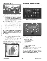
INSTRUMENT AND SWITCH PANEL
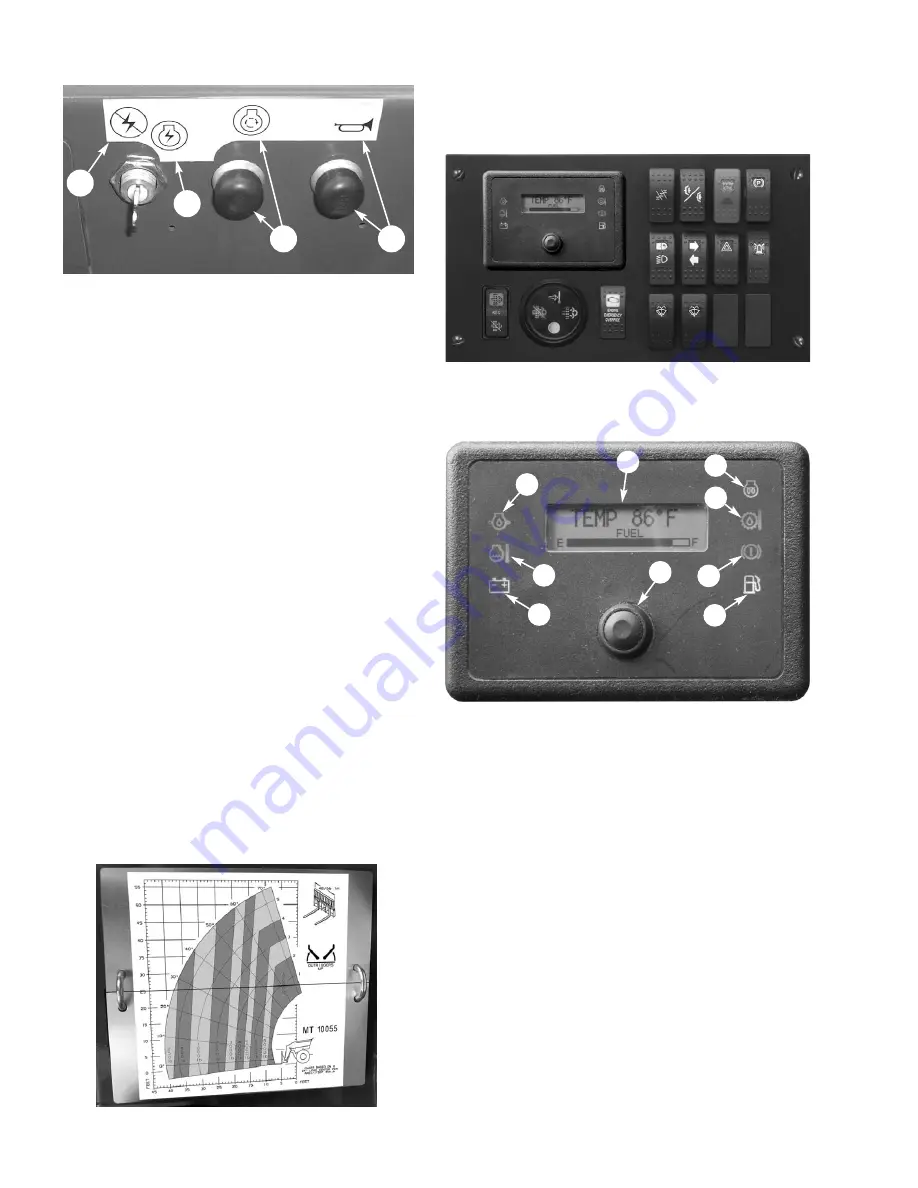
Located to the right of the steering wheel, this panel
contains the instrument gauges, indicator lamps and
function switches.
Instrumentation
A - Multi-Function Display Screen:
This screen dis-
plays the following functions:
•
fuel level at all times,
•
engine coolant temperature,
•
engine oil pressure,
•
voltmeter
•
hourmeter
•
250 hour maintenance reminder
•
error fault codes
B - Scroll Button:
Pressing this button changes the
function displayed in the gauge display panel.
A1 - Fuel Level Gauge:
The fuel level is displayed at
all times in the lower portion of the display. It indicates
the amount of fuel remaining in the fuel tank.
DASH PANEL AREA
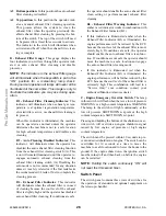
A1 - Key Switch OFF:
When the key is vertical in the
keyswitch, power from the battery is disconnect-
ed to the control and instrument panel electrical
circuits. Also, this is the only position in which
the key can be inserted and removed.
A2 - Key Switch ON:
When the key is turned one
position clockwise from the vertical (OFF) posi-
tion, power from the battery is supplied to all con-
trol and instrument panel electrical circuits. All
indicator lamps in the instrument panel, exhaust
filter gauge and switch and the engine emergency
override switch will illuminate momentarily as a
lamp check.
NOTE:
If the engine requires repeated attempts
to start, the key MUST be returned to the OFF
position between starting attempts to prevent bat-
tery run down.
B - Start Button:
With key switch in ON position,
press the button to activate the starter. Release it
as soon as the engine starts.
C - Horn Button:
With the key switch ON, press the
horn button to activate warning sound.
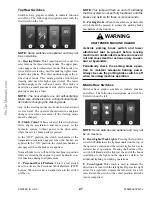
Load Zone Charts:
A series of flip charts show lift
height and reach limits relative to the load weight
being handled with various attachment tools.
Instrument and Switch Panel
A
B
C
G
H
I
D
E
Ignition Switch, Start and Horn Button
A1
C
B
A2
F
Содержание MT10044XT
Страница 12: ...50960025 CP0514 8 PRINTED IN U S A INTENTIONALLY BLANK To be removed as Dealer s file copy ProCarManuals com...
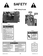
Страница 25: ...PRINTED IN U S A 21 50960025 CP0514 SAFETY 808034 808035 808033 808032 808036 808031 51200535 ProCarManuals com...
Страница 85: ...PRINTED IN U S A 81 50960025 CP0514 Date Hours Service Procedure MAINTENANCE LOG ProCarManuals com...
Страница 86: ...50960025 CP0514 82 PRINTED IN U S A Date Hours Service Procedure MAINTENANCE LOG ProCarManuals com...
Страница 87: ...PRINTED IN U S A 83 50960025 CP0514 Date Hours Service Procedure MAINTENANCE LOG ProCarManuals com...
Страница 91: ...PRINTED IN U S A 87 50960025 CP0913 Hydraulic Schematic for Two Joystick Control without PWP ProCarManuals com...
Страница 92: ...50960025 CP0913 88 PRINTED IN U S A Hydraulic Schematic for Two Joystick Control with PWP ProCarManuals com...
Страница 93: ...PRINTED IN U S A 89 50960025 CP0913 Hydraulic Schematic for Tri Function Joystick without PWP ProCarManuals com...
Страница 94: ...50960025 CP0913 90 PRINTED IN U S A Hydraulic Schematic for Tri Function Joystick with PWP ProCarManuals com...
Страница 95: ...PRINTED IN U S A 91 50960025 CP0913 Electrical Schematic with Radio Remote ProCarManuals com...
Страница 96: ...50960025 CP0913 92 PRINTED IN U S A Electrical Schematic without Radio Remote ProCarManuals com...
Страница 97: ...PRINTED IN U S A 93 50960025 CP0514 INTENTIONALLY BLANK ProCarManuals com...
Страница 108: ...50960025 CP0514 104 PRINTED IN U S A Load Zone Charts MT10055XT Work Platform Decal 50380043 ProCarManuals com...
Страница 114: ...50960025CP0514 2014 Manitou Americas Inc PRINTED IN U S A All Rights Reserved ProCarManuals com...


