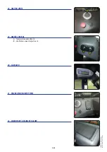
25 - HYDRAULIC CONTROLS FOR ADDITIONAL ATTACHMENTS
IMPORTANT
In the event of a malfunction, consult your dealer.
For your own safety, do not attempt to alter the hydraulic pressure in the system.
ANY MODIFICATION WILL INVALIDATE THE WARRANTY.
The hydraulic controls must be used carefully without jerking, to avoid accidents caused
by shaking the lift truck.
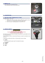
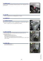
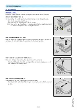
Using the hydraulic controls is only possible if the driver is present and seated correctly
in the seat.
If the operator is not present in the seat, the hydraulic controls are frozen.
NOTE: For lever A (
INSTRUMENTS AND CONTROLS).
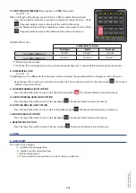
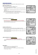
- Pull or push lever B to use the additional attachment(s).
- Press button C to select an attachment
(depending on options)
.
TILTABLE CARRIAGE option
WITHOUT ADDITIONAL HYDRAULIC ATTACHMENT
B1 - OPTIONAL 3RD HYDRAULIC LINE (TILTABLE CARRIAGE)
B2 - OPTIONAL 3RD HYDRAULIC LINE (TILTABLE CARRIAGE)
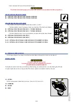
WITH MORE THAN ONE HYDRAULIC ATTACHMENT
- Press button C on lever B to select the attachment AUX.1 or AUX.2:
• The blue indicator lamp C1 coming on indicates activation of the attachment (below).
B1 - OPTIONAL 3RD HYDRAULIC LINE (AUX.1)
B2 - OPTIONAL 3RD HYDRAULIC LINE (AUX.1)
• The blue indicator lamp C1 going out indicates activation of the attachment (below).
B1 - OPTIONAL 4TH HYDRAULIC LINE (AUX.2)
B2 - OPTIONAL 4TH HYDRAULIC LINE (AUX.2)
WITH A SINGLE HYDRAULIC ATTACHMENT
B1 - OPTIONAL 3RD HYDRAULIC LINE
B2 - OPTIONAL 3RD HYDRAULIC LINE
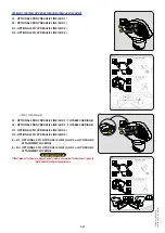
WITH MORE THAN ONE HYDRAULIC ATTACHMENT
- Press button C on lever B to select the attachment AUX.1 or AUX.2:
• The blue indicator lamp C1 going out indicates activation of the attachment (below).
B1 - OPTIONAL 3RD HYDRAULIC LINE (AUX.1 - TILTABLE CARRIAGE)
B2 - OPTIONAL 3RD HYDRAULIC LINE (AUX.1 - TILTABLE CARRIAGE)
• The blue indicator lamp C1 coming on indicates activation of the attachment (below).
B1 - OPTIONAL 4TH HYDRAULIC LINE (AUX.2)
B2 - OPTIONAL 4TH HYDRAULIC LINE (AUX.2)
D + B1 - OPTIONAL 5TH HYDRAULIC LINE (AUX.3)
D + B2 - OPTIONAL 5TH HYDRAULIC LINE (AUX.3)
2-37
C1
C1
C
B
C1
C
B
D
C
A
B
B1
B2
647837 M1 (A052020)
MC 18-2/18-4 D K ST5 S1
Содержание MC 18-2 D K ST5 S1
Страница 1: ...OPERATOR S MANUAL ORIGINAL INSTRUCTIONS EN USM1 A052020 647837 MC 18 2 D K ST5 S1 MC 18 4 D K ST5 S1...
Страница 5: ...1 OPERATING AND SAFETY INSTRUCTIONS 1 1 647837 M1 A052020 MC 18 2 18 4 D K ST5 S1...
Страница 6: ...1 2 647837 M1 A052020 MC 18 2 18 4 D K ST5 S1...
Страница 7: ...1 3 647837 M1 A052020 MC 18 2 18 4 D K ST5 S1...
Страница 25: ...2 DESCRIPTION 2 1 647837 M1 A052020 MC 18 2 18 4 D K ST5 S1...
Страница 26: ...2 2 647837 M1 A052020 MC 18 2 18 4 D K ST5 S1...
Страница 71: ...2 47 647837 M1 A052020 MC 18 2 18 4 D K ST5 S1...
Страница 73: ...3 MAINTENANCE 3 1 647837 M1 A052020 MC 18 2 18 4 D K ST5 S1...
Страница 91: ...3 19 647837 M1 A052020 MC 18 2 18 4 D K ST5 S1...
Страница 97: ...3 25 647837 M1 A052020 MC 18 2 18 4 D K ST5 S1...
Страница 105: ...3 33 647837 M1 A052020 MC 18 2 18 4 D K ST5 S1...
Страница 112: ...3 40 647837 M1 A052020 MC 18 2 18 4 D K ST5 S1...
Страница 113: ...4 OPTIONAL ADAPTABLE ATTACHMENTS FOR THE RANGE 4 1 647837 M1 A052020 MC 18 2 18 4 D K ST5 S1...
Страница 114: ...4 2 647837 M1 A052020 MC 18 2 18 4 D K ST5 S1...
Страница 116: ...4 4 647837 M1 A052020 MC 18 2 18 4 D K ST5 S1...
Страница 119: ...ATTACHMENTGUARDS FORK GUARD PART NO 227801 4 7 647837 M1 A052020 MC 18 2 18 4 D K ST5 S1...
Страница 120: ...4 8 647837 M1 A052020 MC 18 2 18 4 D K ST5 S1...


