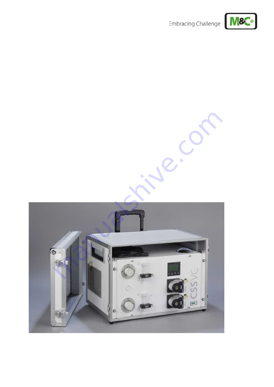
Gas Conditioning Unit Series CSS
®
CSS-VC1, CSS-VC2
19“, wall mount or portable in
carrying case with software
version 1.6
Instruction Manual
Version 1.01.03
Страница 1: ...Gas Conditioning Unit Series CSS CSS VC1 CSS VC2 19 wall mount or portable in carrying case with software version 1 6 Instruction Manual Version 1 01 03 ...
Страница 2: ...t M C or your M C authorized distributor You will find all the addresses in the appendix of this instruction manual For additional information about our products please go to M C s website www mc techgroup com There you can find the data sheets and manuals of our products in German and English This manual does not purport to be complete and is subject to technical changes 05 2020 M C TechGroup Ger...
Страница 3: ...rtable version Part No 01G6190 25 12 4 4 Connecting the optional expansion modules 25 13 Commissioning 25 13 1 Cooler controller 26 14 Decommissioning 27 15 The multifunctional control unit TCU 27 15 1 Basic functions of the TCU 27 15 2 Properties of the TCU 28 15 3 Enhancements to the TCU 28 15 3 1 The communication module 28 15 3 2 The temperature control module 29 15 3 3 The status module 30 15...
Страница 4: ... line DN4 6 with antikink adapter 21 Figure 6 Plug assignment for the version with group alarm Part No 01G6170 22 Figure 7 Upper and lower channel of CSS VC2 23 Figure 8 Plug assignment for design with individual alarms Part No 01G6175 23 Figure 9 Connection examples for alarm outputs 24 Figure 10 Heated line connection for portable version to 10 A 25 Figure 11 Electrical connections communication...
Страница 5: ...r use of this product all information required for technical personnel is contained in this manual 2 DECLARATION OF CONFORMITY CE Certification The product described in this operating manual complies with the following EU directives EMV Instruction The requirements of the EU directive 2014 30 EU Electromagnetic compatibility are met Low Voltage Directive The requirement of the EU directive 2014 35...
Страница 6: ...ot directly expose to dust rain or liquids The device must not be operated in hazardous areas Installation maintenance monitoring and any repairs must be performed by authorised personnel in compliance with the relevant provisions 3 1 INTENDED USE The CSS VC1 and CSS VC2 are intended for use in general purpose areas non hazardous environments They may only be operated in compliance with the inform...
Страница 7: ...ion indicates that an undesirable result or an undesirable situation may occur if the corresponding instructions are not followed Notice This is important information about the product or the appropriate part of the manual to which particular attention should be paid Qualified personnel These are persons with necessary qualification who are familiar with installation use and maintenance of the pro...
Страница 8: ...asses Protect your eyes while working with chemicals or sharp objects Wear safety glasses to avoid getting something in your eyes Wear protective clothes Working with chemicals sharp objects or extremely high temperatures requires wearing protective clothes ...
Страница 9: ...to their equipment and additional options for the wide ranging requirements of continuous gas analysis The entire gas conditioning unit is housed in a compact rugged steel housing so that gas analyses can be performed rapidly without a great deal of effort with low maintenance and reliability Gas conditioning unit CSS VC must not be used to support gas air or gas oxygen mixtures that are ignitable...
Страница 10: ...ssembly unnecessary A portable version is also available in a carrying case Figure 1 Example of a gas flow diagram CSS VC1 Gas cooler series ECM 1 Option universal filter or front installed filter FPF 0 1GF 0 1 μm with optional liquid alarm LA or front installed filter FPF 2 0 3GF 0 3 μm with integrated humidity alarm Option 3 or 5 way ball valve 3L PV or 5L PV Option sample gas pump N3 5 9KPE Opt...
Страница 11: ...uid particle e g CLF 5 W PVDF glass FPM PTFE Sample gas pumps N3 5 9 PVDF PTFE FPM Flow meter FM40 PVDF glass FPM Hastelloy C4 Ball valve 3L PV and 5L PV PVDF FPM Operational Approx 10 minutes Mains connection 230 V 50 60 Hz 10 or 115 V 50 60 Hz 10 Power input Max 220 VA max 300 VA for sample gas pumps Device fuse 6 3 A time lag 5 x 20 mm Electrical connection Cold device connector with 2 m cable ...
Страница 12: ...0 V AC 3 A 2 x small signal digital output for solid state relay control 24 V max 20 mA Function High temperature alarm 2 potential free contacts N O contact 230 V AC 1 A can be used up to 24 V 500 mA Function Low temperature alarm 2 potential free contacts N O contact 230 V AC 1 A can be used up to 24 V 500 mA Function Measurement 1 potential free contact Changeover switch 48 V AC 1 A can be used...
Страница 13: ...060 Extra charge for glass heat exchanger ECM 1 90 for CSS VC1 sample gas connections in the connection plate for e g 19 mount 93K0150 Extra charge for PVDF heat exchanger ECM 1 90 for CSS VC1 sample gas connections in the connection plate for e g 19 mount 93K0170 Extra charge for gas connections of 2 heat exchangers in the connection plate for e g 19 mount 01G6061 Extra charge for glass heat exch...
Страница 14: ...Sample gas pumps max 2 pcs only with evaluation electronic system 01 G 6175 Extra charge for installing sample pumps N KPE 01G6070 Extra charge for sample gas pump N3KPE 01G6125 Extra charge for gas pump N5KPE 01G6130 Extra charge for gas pump N9KPE 01G6135 Flow meter max 4 pc total and flow alarm max 2 pcs Extra charge for installation of a flow meter FM40 7 70 Nl h in the sample gas outlet 09F40...
Страница 15: ...ra charge for backflush module for programmed control of solenoid valves for backflushing of gas probes with status monitoring measuring backflush monitoring of backflush pressure and control of the sample pumps on off 01B8650 Extra charge for M C bus for external modules 01G6180 Transport case 19 version only Extra charge for carrying case for portable gas conditioning 01G6250 Temperature control...
Страница 16: ...ed in a strong compact steel housing for wall or 19 mount The ventilation grilles in the side walls provide adequate forced ventilation Filter flow meter and peristaltic pumps are located in the front panel and thus ensure very simple main tenance Due to a removable lid and a hinged front panel quick and easy inspection and maintenance of all other built in components is possible in particular the...
Страница 17: ...mance levels to choose from N3 5 9 KPE The flow meter FM40 arranged in the sample gas outlet with a measuring range adapted to the pump power can be supplied for flow monitoring with a flow sensor FA 20mo In addition each sample gas line can be equipped with a second sample gas outlet or bypass flow meter and flow control In the event of an aerosol problem a liquid particulate filter CLF can be ad...
Страница 18: ...wnstream analysers and to avoid false alarms the gas conditioning unit should not be used outside the specified temperature range It must also be protected against the ingress and accumulation of dust Downstream analysers and lines must operate at temperatures significantly above the specified gas outlet dew point of 5 C 41 F This will avoid subsequent condensation of the gas in the connecting lin...
Страница 19: ...may also be present for group alarm see Figure 4 The sample gas inlet depending on the version may also lie directly on the heat exchangers Figure 4 Connection group alarm In the portable version of the CSS VC the supply connectors shown above are located on the rear panel of the housing The RJ45 connector is not present here With the temperature controller option for the portable version Part No ...
Страница 20: ...r the condensate hose must be carried out as follows Loosen the clamping ring screwed fitting counterclockwise It is important to ensure that the nut is carefully removed from the threaded joint so that the loose clamping ring which is in the nut is not lost Slide the nut over the hose connection Slide the clamping ring with the thicker bulge facing the nut onto the connection hose Attach the hose...
Страница 21: ... IN bulkhead fitting Pressure ring 6mm Øi Pressure ring 10mm Øi Clip ring 10mm Øi Clip ring 6mm Øi Support sleeve 4mm Junction nut 10mm Øi Heated sample line Adapter Figure 5 Connecting heated line DN4 6 with antikink adapter Place special adapters according to the above drawing on Teflon tubing Slide the support sleeve slide into the Teflon tubing Draw the Teflon tubing all the way into the bulkh...
Страница 22: ...rical connection is via the 2 m 6 56 ft long power cord with cold device connector depending on the mounting of the connection plate either at the back or in the lid of the housing see Section 12 2 12 4 1 GROUP CONNECTION ALARM PART NO 01G6170 The electrical connection of the general alarm condenser fluid and flow is via a 6 pin connector depending on the mounting of the connection plate either at...
Страница 23: ...PERATURE DISPLAY PART NO 01G6175 The electrical connection of the individual alarms is via two connectors depending on the mounting of the connection plate either on the back or in the lid of the housing The corresponding 11 and 12 pin connectors are included The connectors are assigned as follows Figure 8 Plug assignment for design with individual alarms Part No 01G6175 ...
Страница 24: ... connected that a cooler temperature alarm is present excess or low temperature alarm On connector X2 pin 1 2 1 3 1 4 1 5 an indicator can be connected that excess or low temperature alarms of the optional temperature controller module are present On connector X2 1 pin 3 8 3 9 3 10 3 11 respectively an indicator can be connected that flow alarm messages are present Since this is a warning message ...
Страница 25: ... N 4 Mains probe 6 PT100 5 PT100 Figure 10 Heated line connection for portable version to 10 A 12 4 4 CONNECTING THE OPTIONAL EXPANSION MODULES The connection of expansion modules to the CSS VC is via the communication module with the appropriate cable to the RJ 45 socket in the connection panel see Figure 3 The electrical connection of the individual expansion modules is described in Section 15 N...
Страница 26: ...nt in the sample gas a suitable gas sampling probe to protect the sample line from clogging must be provided 13 1 COOLER CONTROLLER Display LED red LED yellow LED green Status message After commissioning 8 C 46 4 F room temperature ON status alarm Lights up in the case of an existing flow alarm OFF Hightemp 1 Pump warn 1 2 when pump is connected and configured accordingly see Section 16 2 After ab...
Страница 27: ... unit TCU in the front panel of the gas conditioning unit CSS VC can undertake a series of different tasks centrally and provide wide ranging system information 15 1 BASIC FUNCTIONS OF THE TCU 1 x temperature controller for the integrated sample gas cooler Evaluation of max 2 liquid alarm sensors Evaluation of max 2 flow monitoring sensors An mA output for external cooler temperature display e g i...
Страница 28: ...S TO THE TCU The TCU can be expanded by up to 4 modules in the range of functions The modules are plugged together according to requirements and provided for rail mounting Warnung Before comissioning exclude that for one channel as well internal as external a PT100 is connected 15 3 1 THE COMMUNICATION MODULE Communication of the TCU with the expansion modules is always with the communication modu...
Страница 29: ...es should be regulated 2 probes or 2 heated lines or 1 probe and 1 heated line so that the controller can be configured accordingly The temperature control module includes 2 additional thermostats e g for control of heated lines or gas sampling probes Control is by control of external solid state relays The module also includes 4 relays for high and low temperature monitoring The connections for t...
Страница 30: ...ssage of the TCU a changeover relay and a solid state relay are connected These can be used for alarm indication In addition external sample gas pumps can be switched off via two further solid state relays e g in the event of an alarm and switched on under good conditions For external control of the pumps see Section 12 4 2 Figure 13 Electrical connections status module ...
Страница 31: ... one second before start and after the end of the programme with which a solenoid valve can be controlled which releases control air to shut off and open the sample gas output of the gas sampling probe with pneumatic valve In addition at the start and end of a backflush programme a changeover relay for status monitoring measuring backflush is switched Here at the TCU dead time can be specified to ...
Страница 32: ...peration without temperature control module If the external temperature controller module has been purchased with the CSS VC under error free normal operation the temperature of the devices to be controlled gas sampling probe probe and or heated sample gas line B line is indicated Figure 16 Front view of the TCU in normal operation with temperature control module From any screen except single temp...
Страница 33: ...ule If the external temperature control module was purchased with the CSS VC there is a choice as to which display will appear here after the PRG key has been pressed once Selection is made with the arrow keys flashing and confirmed by pressing the PRG key again The following displays are available to choose from depending on the controller configuration Cooler temperature Probe temperature Temp h...
Страница 34: ...with the ESC key Here you select the parameter to be taken into consideration for switching off the pump Not taken into consideration x is taken into consideration T1 Pump off with cooler temperature alarm default setting x T2 T3 Pump off with temperature alarms from external temperature control module or Temperature controller for heated line in portable version Art No 01 G 6190 Factory setting x...
Страница 35: ...sh module is switched Interval T2 Period until the next backflush On time T3 Duration of a backflush pulse Off time Duration between backflush pulses Pulse number i Number of resulting backflush pulses cannot be entered Activation Backflush programme is to run on or not off When deactivating Start in 0 is set A programmed backflush runs always automatically after a delay of T1 on two channels Thus...
Страница 36: ...f the arrow key and then 1 x pressing of the PRG key the event list appears in which the last 32 error messages and warnings are listed on 8 pages The individual pages can be seen by using the arrow keys At the bottom of the list of events furthermore the error free time and the total run time operating time counter are displayed The error free time indicates how much time has passed since the las...
Страница 37: ...e version and serial number are displayed By pressing the arrow key again the display of the control temperature reappears 16 6 RESETTING SERVICE AND OPERATING TIME Service and operating time can be reset as follows Press the ESC key and press both arrow keys at the same time The following screen appears Press the PRG key Service life and operating time are reset and Service OK occurs With the ESC...
Страница 38: ... Disconnect the device from the mains Hold the PRG key down and switch the device back on until the message to release the key is displayed The following is displayed 2nd screen Select the parameter to be changed using the arrow key and confirm using the PRG key Use the arrow keys the settings and values can be changed and confirmed with the PRG key Press and hold down the PRG key for 5 seconds to...
Страница 39: ...wing appears in plain text Service required In addition the pending warning is also reported via the individual alarm connection see Section 12 4 2 Language German English French Cooler setpoint temperature 0 7 C 32 F 44 6 F default setting 5 C 41 F Temperature channel 2 temperature range dependent on sensor type see below default setting 180 C 356 F Temperature channel 3 temperature range depende...
Страница 40: ...the liquid alarm LA Alarm 1 2 can trigger the pump alarm Pump Warn 1 2 and that in turn can trigger the flow alarm FA Warn 1 2 The comm error e g interrupted connection cable RJ45 causes temperature sensor range exceeded T max 2 3 and flushing pressure alarm flushing pressure not present as temperature sensors and pressure sensors are connected to the communication module From this follows the tem...
Страница 41: ... red Temperature sensor measuring range fallen below sensor defective For channels 2 and 3 appears when the control temperature is fallen below 10 C 50 F alarm hysteresis of the following screen This prevents the heated line or the heated probe from overheating due to a defect The triggered alarm red LED must be acknowledged by pressing any key If the error is not corrected the error screen comes ...
Страница 42: ...intenance interval expired Comm Error x red Error on connecting cable RJ45 between CSS VC and communication module Flushing pressure not present x yello w Pressure for probe backflushing too low or non existent Thermal Error 2 3 x red Thermocouple set and defective or not connected or PT100 connected 18 MAINTENANCE Before performing maintenance work the system and process specific safety measures ...
Страница 43: ...NGE THE FILTER ELEMENTS AND O RINGS To change the filter elements and O rings Unplug the gas conditioning unit from the mains Unscrew filter glass Unscrew filter element with filter holder Exchange filter element and or O ring s Ensure correct seating of filter element and O ring s Screw glass filter cap back 18 2 MAINTENANCE OF THE SAMPLE GAS PUMP S Diaphragm and valve plates are the only pump pa...
Страница 44: ...m Figure 17 Maintenance of sample gas pump s Loosen hoses on the pump head mount sic any existing flow chamber s with mounting plate from the stud bolts Figure 18 Sectional drawing N3 5 KPE and N9 KPE 3 4 2 9 1 13 16 14 11 7 8 N9 KPE N3 5 KPE ...
Страница 45: ...not fall from the threaded bolt of the structure diaphragm into the housing Remove adjusting washer s 11 from the threaded bolt of the structure diaphragm and keep Inspect all parts for contamination and clean if necessary Place the adjusting washer s onto the threaded bolts of the new structure diaphragm Move the connecting rod 13 into the top dead centre position Screw the new structure diaphrag...
Страница 46: ...mp by turning the fan wheel Move structure diaphragm via fan wheel into the top dead centre dead point position Now hand tighten the screws 4 18 2 5 CLEANINGTYPE N 3 5 9 KPE On changing valve plates and diaphragm prior to assembly of the pump head all parts should be checked for contamination and cleaned if necessary Wipe the parts as dry as possible with a cloth Solvents should not be used when c...
Страница 47: ...6 1 01 03 47 18 3 MAINTENANCE OF THE BUILT IN PERISTALTIC PUMP TYPE SR 25 2 Pump hose belt pressure rollers and springs are the only wear parts of the pump They are easy to change Figure 19 Components of the peristaltic pump SR25 2 ...
Страница 48: ... Pump motor inside the device housing Figure 20 SR25 2 Mounting distance between front panel and pump motor Note For detailed mounting instructions see the instruction manual for the peristaltic pump series SR The manual is available on our website www mc techgroup com 18 3 2 EXCHANGE THE PUMP HOSE Warning Aggressive media residues possible On disassembly repairing or cleaning of the hose pump wea...
Страница 49: ...ure rollers and see if spring tension exists if not change pressure springs see Section 18 3 3 Insert new pump hose with slip fittings into the guides of the belt Warning Only the use of original spare pump hose ensures proper function Never lubricate the pump hose Check all parts for dirt before assembling the hose pump and clean if necessary Insert belt complete with the new hose into the doveta...
Страница 50: ...mount roller axes and change contact pulleys Take care that axes are not worn out by the springs and have damaged the dent at the axes front end In case of abrasion the axes have to be changed see Figure 23 Figure 23 Check of axes and rolls Note The springs may occur in different colorings This does not constitute a quality defect But make sure that the right spring strength is used This can be id...
Страница 51: ...nted as shown in Figure 23 Please pay attention to the alignment of the dent Remounting happens in reverse order Note While mounting pay attention to the fit of rotational axisdriver and check that the plunged boss at the shaft bore points to the front of the pump head Use genuine spare parts only 18 3 4 CLEANING THE PUMP HEAD We recommend that you clean the individual parts with a dry wipe Solven...
Страница 52: ...ent reduction in cooling performance the cooling fins of the compressor cooler must be cleaned of dust regularly To do this blow compressed air on the right side in the housing into the ventilation grille Notice With clean cooling fins an A4 sheet of paper is sucked onto the grille on the right housing side and sticks ...
Страница 53: ...e F 2GF Length 75 mm material Fiberglass filter fineness 2μm Pack of 25 pcs For assembly 2 x adapter rings type No 93S0050 are required R 1 2 3 90F0016 Filter element type F 0 1GF Length 64 mm material Fiberglass filter fineness 0 1 µm For assembly 2 x adapter rings Art No 93S0050 are required R 6 12 18 90F0550 Filter element type F 0 05SIC Length 75 mm material Ceramic filtration fineness 0 05 µm...
Страница 54: ...Viton C 2 4 6 Peristaltic pump SR25 2 90P1007 SR25 pump hose with PVDF hose connector DN 4 6 mm C 1 2 4 90P1010 1 set of pressure springs for roller support of SR25 2 set 4 pieces C 1 2 3 90P1020 Roller support complete for SR25 2 R 1 90P1045 Pressure roller 1 pc for SR25 2 C 2 4 90P1050 Belt for SR25 2 S 1 1 1 90P1025 S lock for SR25 2 S 1 1 1 90P1031 Hose pump head complete for SR25 2 without sy...
Страница 55: ...the appropriate disposal of obsolete electrical and non electrical devices To help protect our environment please follow the rules and regulations of your country regarding recycling and waste management 21 APPENDIX Incident messages and their meaning TCU menu Further product documentation can be viewed and accessed on the home page www mc techgroup com ...
Страница 56: ...mperature does not rise defective thermocouple Th3 Error If thermocouple is connected and temperature does not rise thermocouple is faulty T1 Temp min T1 70 C possible short circuit T2 Temp min T2 50 C possible short circuit T3 Temp min T3 50 C possible short circuit Warnings Event message Significance T2 low warning T2 low temp outside of hysteresis T3 low warning T3 low temp outside of hysteresi...
Страница 57: ... OK T1 Temp min T1 Temp min T1 70 C T2 Temp min T2 Temp min T2 50 C T3 Temp min T3 Temp min T3 50 C Th3 OK Thermocouple 3 is OK Cancellation of warnings Event message Significance T2 L warning OK T2 now has no low temperature T3 L warning OK T3 now has no low temperature Device OK Device within the operating temperature 1 C T 50 C FA1 OK Flow channel 1 OK FA2 OK Flow channel 2 OK Pump1 OK Pump1 ru...
Страница 58: ...ion module is back P1 man On Pump 1 is set to On P1 man Off Pump 1 is set to off P2 man On Pump 2 is set to On P2 man Off Pump 2 is set to off P1 ext On Pump 1 external active P1 ext Off Pump 1 external inactive P2 ext On Pump 2 external active P2 ext Off Pump 2 external inactive P1 auto Appears when ON or OFF is disabled in the pump menu P2 auto Appears when ON or OFF is disabled in the pump menu...
Страница 59: ...www mc techgroup com CSS VC 1 6 1 01 03 59 Figure 24 TCU menu ...