5
6
7
Removing and installing turbocharger
88
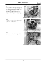
Fig. 5
Release the four (self-locking) nuts (WAF 17) on
the turbocharger flange.
Take off turbocharger.
Note:
When placing the turbocharger to one
side, ensure extreme cleanliness to pre-
vent penetration of dirt and foreign
bodies.
Installing turbocharger
Fig. 6
The turbocharger is fitted in reverse order.
On assembly, new seals and new self
−
locking nuts
are to be used.
Tightening torque: 85 Nm
Before connecting the oil supply line, fill the bea-
ring housing with fresh engine oil.
Fig. 7
Connect the charge-air manifold and intake neck.
Check all the connections for leaks and to ensure
they are not subjected to strain.
Note:
Charge pressure is lost through leaking
charge air pipes. The consequences are
black smoke and a drop in performance.
Caution:
Comply with instructions for masking
unions on pressurised oil and fuel pipes
(see page 3).
Содержание D 2840 LE 301
Страница 1: ......
Страница 2: ......
Страница 16: ...Notes 14...
Страница 20: ...Engine views 18 Engine views D 2842 LE 301 9 10 11 12 9 8 6 5 4 3 2 1 13 14 15 16 17 18 6 7 8...
Страница 150: ...Notes 148...
Страница 151: ...149 Service Data...
Страница 179: ...177 Special tools...
Страница 180: ...Special tools 178 2 3 4 5 6 7 8 1 6 1 6 2 6 3 9 1 9 2 9 3 9...
Страница 182: ...Special tools 180 10 11 16 14 14 1 12 13 18 18 1 12 1 12 2 15 5 15 4 15 1 15 1 15 2 15 3 15 3 15 6 15 7 15 17...
Страница 184: ...Special tools 182 21 22 25 25 2 24 25 1 26 27 1 27 2 27 20 1 19 2 19 1 20 2 19 20 28 23...
Страница 186: ...Special tools 184 30 29 32 31 33...
Страница 189: ...Special tools 187 2843 Pressing mandrel for cap dia 50 1 mm Pressing mandrel for cap dia 62 1 mm...
Страница 193: ......
Страница 194: ......


