


5 - 4
5.3
Basic Troubleshooting
Troubleshooting is the logical elimination of all necessary steps in a pro-
cess or the potential variables within a step until the “Fault” is uncovered.
1. When a fault arises, gather as much information as possible about the
events leading up to the fault. This often eliminates many steps in the
troubleshooting process.
2. Determine where the fault resides. “Is this a Machine or CNC fault?”
3. Begin with the basic question of whether power exists. If power does
not exist, ask the following questions:
-
Is there power at the source? – Check power at the source.
-
Is there power to the machine? –Check power at the main discon-
nect on the machine, refer to the schematics.
-
Is there power to the control? – Check the CNC Maintenance Man-
ual for details, see
4. After confirming that power exists and the control and machine are
“On,” ask:
-
Is the machine
READY
? – See
-
Is the control
READY
.
Continuing in this manner should lead to the source of the Fault.
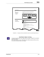
If in doubt, it is always safe to start at the beginning. The flow chart, in
, will prove helpful in beginning the troubleshooting process.
If the machine and control are both READY and an alarm is generated,
finding the cause of the fault is greatly simplified:
1. Determine if the alarm is a CNC alarm or a Machine alarm.
2. Look up the proper alarm listing in
If no alarm is displayed use the other available troubleshooting tools dis-
cussed in
Notes for Figure 5-1
1. Machine and CNC alarms are listed in
of this Maintenance Guide.
2. Refer to the CNC Maintenance Manual for more detail on CNC alarms.
Содержание V55
Страница 6: ...vi...
Страница 32: ...1 24 NOTES SKETCHES...
Страница 37: ...4V2A1563 E 2 3 FIGURE 2 1 SPINDLE POWER AND TORQUE CHARACTERISTICS...
Страница 39: ...4V2A1563 E 2 5 FIGURE 2 2 AXIS CONFIGURATION TRAVEL AND WORK CUBE...
Страница 41: ...4V2A1563 E 2 7 FIGURE 2 4 WORKPIECE SIZE LIMITATIONS...
Страница 53: ...4V2A1563 E 2 19 FIGURE 2 6 FLOOR SPACE FOR STANDARD MACHINE...
Страница 58: ...2 24 F IGURE 2 7 V55 WITH 25 TOOL ATC...
Страница 59: ...4V2A1563 E 2 25 F IGURE 2 8 V55 WITH 25 TOOL ATC AND LIFT UP CHIP CONVEYOR LEFT...
Страница 60: ...2 26 F IGURE 2 9 V55 WITH 25 TOOL ATC AND LIFT UP CHIP CONVEYOR RIGHT...
Страница 61: ...4V2A1563 E 2 27 F IGURE 2 10 V55 WITH 25 TOOL ATC LIFT UP CHIP CONVEYOR LEFT AND APC...
Страница 62: ...2 28 F IGURE 2 11 V55 WITH 25 TOOL ATC LIFT UP CHIP CONVEYOR RIGHT AND APC...
Страница 63: ...4V2A1563 E 2 29 F IGURE 2 12 V55 WITH 40 OR 80 TOOL ATC...
Страница 64: ...2 30 F IGURE 2 13 V55 WITH 40 OR 80 TOOL ATC AND LIFT UP CHIP CONVEYOR LEFT...
Страница 65: ...4V2A1563 E 2 31 F IGURE 2 14 V55 WITH 40 OR 80 TOOL ATC AND LIFT UP CHIP CONVEYOR RIGHT...
Страница 66: ...2 32 F IGURE 2 15 V55 WITH 40 OR 80 TOOL ATC LIFT UP CHIP CONVEYOR LEFT AND APC...
Страница 67: ...4V2A1563 E 2 33 F IGURE 2 16 V55 WITH 40 OR 80 TOOL ATC LIFT UP CHIP CONVEYOR RIGHT AND APC...
Страница 68: ...2 34 NOTES SKETCHES...
Страница 93: ...4V2A1563 E 3 23 FIGURE 3 6 LEVELING BASE POSITIONS AND BED TO FLOOR CLEARANCE...
Страница 94: ...3 24 NOTES SKETCHES...
Страница 99: ...4V2A1563 E 4 3 FIGURE 4 1 MACHINE CORE ELEMENTS...
Страница 103: ...4V2A1563 E 4 7 FIGURE 4 3 MAKINO PROFESSIONAL 3 CONTROL WITH MPC5...
Страница 106: ...4 10 NOTES SKETCHES...
Страница 114: ...4 18 NOTES SKETCHES...
Страница 123: ...4V2A1563 E 5 5 FIGURE 5 1 BASIC TROUBLESHOOTING FLOW CHART...
Страница 124: ...5 6 NOTES SKETCHES...
Страница 143: ...4V2A1563 E 5 25 NOTES SKETCHES...
Страница 153: ...4V2A1563 E 5 35 NOTES SKETCHES...
Страница 159: ...4V2A1563 E 5 41 NOTES SKETCHES...
Страница 166: ...5 48 NOTES SKETCHES...
Страница 191: ...4V2A1563 E 5 73 TEC F IGURE 5 26 S CHEMATIC PAGE FORMAT...
Страница 197: ...4V2A1563 E 5 79 NOTES SKETCHES...
Страница 198: ...5 80 NOTES SKETCHES...
Страница 202: ...NOTES SKETCHES...
Страница 227: ...4V2A1563 E 6 25 NOTES SKETCHES...
Страница 252: ...6 50 NOTES SKETCHES...
Страница 261: ...4V2A1563 E 6 59 FIGURE 6 36 SPINDLE HYDRAULIC CIRCUIT...
Страница 267: ...4V2A1563 E 6 65 FIGURE 6 40 L PORT SPINDLE LUBRICATION...
Страница 269: ...4V2A1563 E 6 67 FIGURE 6 41 V PORT SPINDLE LUBRICATION...
Страница 277: ...4V2A1563 E 6 75 NOTES SKETCHES...
Страница 279: ...4V2A1563 E 6 77 FIGURE 6 48 SEALING ROD INSTALLATION...
Страница 284: ...6 82 NOTES SKETCHES...
Страница 293: ...4V2A1563 E 7 5 F IGURE 7 3 AXIS DRIVE CIRCUIT...
Страница 297: ...4V2A1563 E 7 9 NOTES SKETCHES...
Страница 309: ...4V2A1563 E 7 21 FIGURE 7 12 BALL SCREW COOLING OIL AND TAC BEARING LUBRICATION PIPING...
Страница 311: ...4V2A1563 E 7 23 NOTES SKETCHES...
Страница 317: ...4V2A1563 E 7 29 FIGURE 7 18 BALL SCREW PRE TENSION PROCEDURE...
Страница 331: ...4V2A1563 E 7 43 FIGURE 7 26 Y AXIS LIMIT SWITCH TO DOG SETTINGS FIGURE 7 27 Z AXIS LIMIT SWITCH TO DOG SETTINGS...
Страница 346: ...7 58 NOTES SKETCHES...
Страница 348: ...7 60 FIGURE 7 35 Y AXIS COVER SYSTEM...
Страница 351: ...4V2A1563 E 7 63 NOTES SKETCHES...
Страница 369: ...4V2A1563 E 7 81 NOTES SKETCHES...
Страница 370: ...7 82 NOTES SKETCHES...
Страница 374: ...NOTES SKETCHES...
Страница 386: ...8 12 NOTES SKETCHES...
Страница 403: ...4V2A1563 E 8 29 NOTES SKETCHES...
Страница 423: ...4V2A1563 E 8 49 NOTES SKETCHES...
Страница 432: ...8 58 NOTES SKETCHES...
Страница 439: ...4V2A1563 E 9 5 NOTES SKETCHES...
Страница 441: ...4V2A1563 E 9 7 F IGURE 9 3 OIL CONTROLLER ELECTRICAL DRAWINGS...
Страница 443: ...4V2A1563 E 9 9 FIGURE 9 4 OIL CONTROLLER MACHINE SYSTEM...
Страница 464: ...9 30 NOTES SKETCHES...
Страница 468: ...NOTES SKETCHES...
Страница 490: ...A 22 NOTES SKETCHES...
Страница 525: ...4V2A1563 E A 57 NOTES SKETCHES...
Страница 526: ...A 58 NOTES SKETCHES...
Страница 534: ...B 6 NOTES SKETCHES...
Страница 546: ...B 18 NOTES SKETCHES...
Страница 558: ...B 30 NOTES SKETCHES...
Страница 564: ...B 36 NOTES SKETCHES...
Страница 568: ...B 40 NOTES SKETCHES...


