


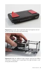


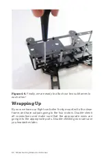


Figure 4-6.
Each motor has a dedicated output and rotation
direction; the APM unit and the APM diagram are both pointing
in the same forward direction.
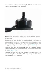
To properly route these cables, take a small paint pen or Sharpie
and label each ESC plug with its corresponding output number.
Once they are clearly labeled, align the tips of all the plugs and
place a small zip tie or two along the cable length just below the
plugs. This will help keep everything neat and organized. Now
push that group of cables through one of the four rectangular
holes in the back of the clean frame (near the APM output pins).
See
for a detailed photo of this process.
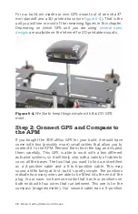
Now, simply plug each of the ESC plugs in to the APM output
that you labeled earlier. If you followed these steps correctly,
you should have a nice neat connection between your APM and
the aircraft’s ESCs, similar to
. Notice the attention we
paid to keep the wiring as neat as possible. A clean build is eas-
ier to work on.
Flight Controller 87
Содержание Belinda Kilby
Страница 1: ......
Страница 3: ...Make Getting Started with Drones Terry Kilby and Belinda Kilby...
Страница 25: ...Figure 1 5 Basic quadcopter showing how the stick commands would move the craft Introduction 13...
Страница 26: ......
Страница 90: ......
Страница 126: ......
Страница 142: ...Figure 8 7 Mobius camera next to the quick release camera mount 130 Make Getting Started with Drones...
Страница 146: ...Figure 9 4 Firmware upload has begun Figure 9 5 Firmware verification in progress 134 Make Getting Started with Drones...
Страница 153: ...Figure 9 10 Compass setup Figure 9 11 Compass calibration ArduPilot Mega APM Setup 141...
Страница 198: ......


