Major Science SmartView Pro 2300 Скачать руководство пользователя страница 1


SmartView Pro 2300/2400 

  Imager System 


Instruction Manual 

Catalogue No. 


UVCI-2300 


UVCI-2400 


www.majorsci.com 

[email protected] 


Version 07A 

Revised on : 2018/11/07 


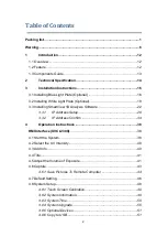
Содержание SmartView Pro 2300

Страница 1: ...SmartView Pro 2300 2400 Imager System Instruction Manual Catalogue No UVCI 2300 UVCI 2400 www majorsci com service majorsci com Version 07A Revised on 2018 11 07...

Страница 2: ...2300 Imager system 1 x 2 0MP CCD camera and lens 1 x 312 302 nm UV transilluminator 1 x Epi White Light Module 1 x UV viewing window SmartView Pro 2400 Imager system 1 x 2 0MP CCD camera and lens 1 x...

Страница 3: ...sis Software 22 3 3 1 IP Address Setup 28 3 3 2 IP Address Confirm 34 4 Operation Instructions 38 HMI Interface UVCI 2300 38 4 1 Start the System 38 4 2 Select the UV Intensity 40 4 3 Add Info 40 4 4...

Страница 4: ...59 4 13 3 Flip horizontally 59 4 13 4 Turn counterclockwise 60 4 13 5 Turn clockwise 60 4 13 6 Brightness adjust 60 4 13 7 Crop 61 4 13 8 Text 61 4 13 9 Undo and redo 63 4 14 Signals Indication 63 4 1...

Страница 5: ...82 4 13 1 Anti white 84 4 13 2 Flip upside down 84 4 13 3 Flip horizontally 84 4 13 4 Turn counterclockwise 85 4 13 5 Turn clockwise 85 4 13 6 Brightness adjust 85 4 13 7 Crop 86 4 13 8 Text 86 4 13...

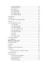
Страница 6: ...5 8 Ordering Information 141 9 Warranty 142...

Страница 7: ...in accordance with the instructions may cause harmful interference to radio communications However there is no guarantee that interference will not occur in a particular installation If this equipment...

Страница 8: ...lly before operating this equipment 1 Read and follow the manual instructions carefully 2 Do not alter the equipment Failure to follow these directions could result in personal and or laboratory hazar...

Страница 9: ...Avoiding Electrical Shock Follow the guidelines below to ensure safe operation of the unit SmartView Pro Imager System series has been designed to use with shielded wires thus minimizing any potentia...

Страница 10: ...see if the unit is functioning correctly before using this unit 2 NEVER access dangerous chemicals or other materials to prevent possible hazard of explosion and damage 3 A temporary conductivity caus...

Страница 11: ...s properly protected Indicates disposal instruction DO NOT discards this unit into a municipal trash bin when this unit has reached the end of its lifetime To ensure utmost protection of the global en...

Страница 12: ...t put the machine near the table edge Move the machine by cart Pinch Do not put your hands on the open door Slash Prevent hard impact on the acrylic panel UV radiation dangerous Do not open the darkro...

Страница 13: ...ne touch image capture and user friendly software interface The expendable accessories such as epi blue module and White Light Plate are also available for environment safe nucleic acid stains or west...

Страница 14: ...13 1 3 Components Guide Rear View Side View CCD camera and lens Darkroom door Touch panel Viewing window Power socket Fuse holder Power switch USB port Front View Inching switch of the door UVCI 2300...

Страница 15: ...USB flash drive Front x 1 Back x 2 all three ports Supports Mitsubishi thermal printer P95DW Material Painted iron metal ABS front door Rated Voltage 100 240V 50 60Hz 2A Safety Regulation CE Stylus P...

Страница 16: ...filters should be used Darkroom Built in Drawer Type UV transilluminator 312 302 nm Light source 8W 6 tubes Built in Blue light Table Built in LED white light Light source 1W x 6 lamps UV Safety door...

Страница 17: ...pansion to offer higher flexibility There are few procedures to install the optional devices place the unit on a sturdy level safe and dry place then follow the instruction below for installation Note...

Страница 18: ...ht Plate 17 Step2 Open the darkroom door The Blue Light Plate will be installed under the White Light Plate Step3 Fasten the Blue Light Plate onto device with a regular screwdriver and four screws Whi...

Страница 19: ...3 1 3 2 Installing Optional Light Plate 18 Step4 Connect the Blue Light Plate cable to darkroom inner socket NOTICE Blue Light Plate cable connects to the upper socket Finished...

Страница 20: ...ght Plate 19 3 2 Installing White Light Plate Optional Step1 Get the White Light Plate ready Step2 Open the darkroom door Place the White Light Plate as the picture below Align four screw holes in yel...

Страница 21: ...Plate 20 Step3 Fasten the White Light Plate onto device with a regular screwdriver and four screws Step4 Connect the White Light Plate cable to darkroom inner socket NOTICE White Light Plate cable con...

Страница 22: ...3 1 3 2 Installing Optional Light Plate 21 Note If necessary please manually adjust the aperture to have the best performance while working with White Light Table Aperture ring F1 2 Close...

Страница 23: ...type Change User Account Settings or Go to Control Panel User Accounts and Family Safety User Accounts 2 Do one of the following To turn off UAC move the slider to the Never notify position and then c...

Страница 24: ...Installing SmartView 1D Analysis Software 23 Step2 Activate SmartView 1D Analysis Software installation program Step3 Click Next to proceed Step4 Accept the license agreement then press Next to proce...

Страница 25: ...3 3 Installing SmartView 1D Analysis Software 24 Step5 Save this program in your specifying location then press Next to proceed Step6 Click Install to begin the installation...

Страница 26: ...ress Finish to complete the program installation Step8 A dialog will pop up to ask you to restart your system press Yes to restart now or No if you plan to manually restart later Note Please restart t...

Страница 27: ...ill be shown on desktop Step10 Click to open SmartView 1D Analysis Software For the first installation you will need to enter the corresponding IP address of your device and license key Press OK to fi...

Страница 28: ...ress Find your license key as following instruction Note The license key must match the camera serial number Note Do not unplug the Ethernet cord of SmartView Pro Imager System when you operate the an...

Страница 29: ...he installation So we suggest user check the IP address of user s computer Follow the instructions below Step1 Open Control Panel on the computer Enter Network and Internet then Network and Sharing Ce...

Страница 30: ...struction UVCI 2300 29 Step2 Click on Change adapter settings User can see the connected LAN Local Area Network Enabled means the network that user s computer is using and the network is connected Ste...

Страница 31: ...2300 30 Step3 Right click on the connected network and select Properties The Network properties dialogue will pop up on the screen Step4 Select Internet Protocol Version 4 TCP IPv4 then click Propert...

Страница 32: ...mputers To set up a new IP address the first 3 numbers should be the same as the first 3 numbers of user s network IP address All user need is to change the last number which has to be different from...

Страница 33: ...10 0 0 166 Then the IP address of user s computer should be set up like 10 0 0 152 User can use the numbers ranging from 1 to 254 except 103 the conflicted IP address and 166 the UVCI 2300 2400 IP add...

Страница 34: ...Operation Instruction UVCI 2300 33 Step6 After finishing the setting press OK to confirm the settings and exit the dialogue...

Страница 35: ...VCI 2300 34 3 3 2 IP Address Confirm To confirm the new IP address Follow the next step Step7 Click on the Start button Type cmd in the search bar and press Enter key to execute the program MS DOS wil...

Страница 36: ...ystem then shows the IP address of user s the example in step 5 user s IP has been changed to 10 0 0 152 therefore the same IP address is showed in the screen However if it is not showed on the screen...

Страница 37: ...ance the IP address of the used UVCI 2300 2400 is 10 0 0 166 then type ping 10 0 0 166 and press Enter Step11 The program will start connecting user s computer to UVCI 2300 2400 The information showed...

Страница 38: ...ion UVCI 2300 37 If the network is still not connected please check the connection and settings of user s network equipment This means the network is not working computer and controller are not connec...

Страница 39: ...on Instruction UVCI 2300 38 4 Operation Instructions HMI Interface UVCI 2300 4 1 Start the System Plug on power cord to your socket Turn on device via the power switch on side of UVCI 2300 Opening Int...

Страница 40: ...Operation Instruction UVCI 2300 39 HMI Interface optional devices disabled HMI Interface optional devices enabled With white light plate and blue light plate optional devices connected...

Страница 41: ...100 to set the UV light intensity 4 3 Add Info Press Add Info icon to enable the function of date exposure time stamp on the left corner of picture and the title on the middle above If user wants to...

Страница 42: ...Operation Instruction UVCI 2300 41 4 4 Title Press Title icon to rename the title 4 5 Adjust the Volume of Exposure Key in the desired value of exposure time 0 001 30 sec...

Страница 43: ...Operation Instruction UVCI 2300 42 Press or under the column of Exposure to increase decrease 0 001 sec of the value of exposure user sets...

Страница 44: ...Operation Instruction UVCI 2300 43 4 6 Capture Press Capture icon to capture a picture at the present The capture dialogue would pop out A B C...

Страница 45: ...characters Select either 8 bit or 16 bit and the file format user would like to save Note All file format can be saved as 8 bit while only tiff and png can be saved as 16 bit Click Save to apply or C...

Страница 46: ...d change your user name and password by checking your UVCI 2300 2400 interface Default Setting Remote login 4 List of current pictures saved in Internal disk then could be viewed and saved from the co...

Страница 47: ...tems as default setting See detailed description below Start up settings In this column user can set the lighting module on or off as default setting Also user can set the intensity of UV light UVCI 2...

Страница 48: ...bit 16 bit for tiff and png only Remote login When user wants to save pictures from remote computer it is necessary to input the user name and the password first Here user can change user name and pa...

Страница 49: ...Operation Instruction UVCI 2300 48 4 8 System Setup System Setup Page Press System Setup icon and open the system setup page See detailed description in the following sections...

Страница 50: ...system will transfer to the page of screen calibration Click the middle of the cross until finish the calibration process After finish the screen calibration process system will return to the prior pa...

Страница 51: ...m time Press Set to save or Cancel to cancel and close the dialogue If there is a need of system upgrade plug the USB with the upgrade file in and press If user does not plug in the USB or the USB doe...

Страница 52: ...all files to a flash drive select the files plug the USB on then press Plug the USB with upgrade file system will pop up a warning to confirm press Yes to continue or No to cancel NOTE System will re...

Страница 53: ...irst otherwise this button will not show up 4 8 10 Screen Saver Click to set the screen saver time The window below will be shown Time setting range is 3 9999 min 4 8 11 Create Folder If user would li...

Страница 54: ...Operation Instruction UVCI 2300 53 4 8 12 Remove Folder If user would like to delete any folder in the list select the folders and press...

Страница 55: ...0 54 4 8 13 Network Settings Press to set detail information Press Apply to apply or Cancel to cancel and close the dialogue 4 9 Reverse out Press the icon to reverse the color of present picture from...

Страница 56: ...press Capture and press Save During the period of freeze the UV light function can not be activated If the UV light were lit it would be temperately shut off press freeze button again to resume UV lig...

Страница 57: ...11 Turn ON OFF the Lighting Modules Press the icon of Epi White Light to turn on off the Epi white light Press the icon of White Light Plate to turn on off the white light Press the icon of Blue Light...

Страница 58: ...tomatically only by pressing Print button 4 13 Load and Edit the Picture Press Load icon to review or edit the files in device or flash drive Select either Internal Disk or External USB Disk to read t...

Страница 59: ...Operation Instruction UVCI 2300 58 Editing Interface Close Cancel Save Anti white Flip upside down Flip horizontally Turn counterclockwise Turn clockwise Brightness adjust Crop Text...

Страница 60: ...tion Instruction UVCI 2300 59 4 13 1 Anti white 4 13 2 Flip upside down 4 13 3 Flip horizontally Press to anti white the screen Press to turn the picture upside down Press to flip the picture horizont...

Страница 61: ...I 2300 60 4 13 4 Turn counterclockwise 4 13 5 Turn clockwise 4 13 6 Brightness adjust Press to turn the picture counterclockwise Press to turn the picture clockwise Press to increase or decrease the b...

Страница 62: ...minimum area of cropping is 256 256 pixels If the crop square shows red it is too small if it is green it is in possible size 1 Press to create a new text on the picture Locate one point and press to...

Страница 63: ...t in the column is to backspace Press Cancel to cancel editing and close 4 Press to adjust the front size Press Apply to confirm or Cancel to cancel and close the dialogue 5 Press to change the color...

Страница 64: ...y changing can be undone or redone by buttons along right bar If the UV transilluminator is on while the door is opened UV light will be turned off automatically and the warning will pop up to warn us...

Страница 65: ...Operation Instruction UVCI 2400 64 HMI Interface UVCI 2400 4 1 Start the System Plug on power cord to your socket Turn on device via the power switch on side of UVCI 2400 Opening Interface...

Страница 66: ...Operation Instruction UVCI 2400 65 HMI Interface optional device disabled HMI Interface optional device enabled With optional device white light plate connected...

Страница 67: ...ction of date exposure time stamp on the left corner of picture and the title on the middle above If user wants to show only certain item press to enter Default Setting Add Info for further changing 4...

Страница 68: ...ruction UVCI 2400 67 4 5 Adjust the Volume of Exposure Press or under the column of Exposure to increase decrease 0 001 sec of the value of exposure user sets Key in the desired value of exposure time...

Страница 69: ...he present A Select either Internal disk or External USB to decide the loction of the storage B Tap the button behind Save in folder to choose the folder that desired to be saved Note Users could crea...

Страница 70: ...o apply or Cancel to cancel and close the dialogue 4 6 1 Save Pictures To Remote Computer User could save pictures in Internal disk to any computer as long as UVCI 2400 is connected to a wireless rout...

Страница 71: ...name and the password NOTICE You may find and change your user name and password by checking your UVCI 2300 2400 interface Default Setting Remote login 4 List of current pictures saved in Internal di...

Страница 72: ...an set various items as default setting See detailed description below Start up settings In this column user can set the lighting module on or off as default setting User can set the auto shut off tim...

Страница 73: ...bit 16 bit for tiff and png only Remote login When user wants to save pictures from remote computer it is necessary to input the user name and the password first Here user can change user name and pa...

Страница 74: ...Operation Instruction UVCI 2400 73 4 8 System Setup Press System Setup icon and open the system setup page See detailed description in the following sections System Setup Page...

Страница 75: ...m will transfer to the page of screen calibration Click the middle of the cross until finish the calibration process After finish the screen calibration process system will return to the prior page au...

Страница 76: ...m time Press Set to save or Cancel to cancel and close the dialogue If there is a need of system upgrade plug the USB with the upgrade file in and press If user does not plug in the USB or the USB doe...

Страница 77: ...all files to a flash drive select the files plug the USB on then press Plug the USB with upgrade file system will pop up a warning to confirm press Yes to continue or No to cancel NOTE System will re...

Страница 78: ...irst otherwise this button will not show up 4 8 10 Screen Saver Click to set the screen saver time The window below will be shown Time setting range is 3 9999 min 4 8 11 Create Folder If user would li...

Страница 79: ...Operation Instruction UVCI 2400 78 4 8 12 Remove Folder If user would like to delete any folder in the list select the folders and press...

Страница 80: ...Operation Instruction UVCI 2400 79 4 8 13 Network Settings Press to set detail information Press Apply to apply or Cancel to cancel and close the dialogue...

Страница 81: ...se the color of present picture from black to white white to black 4 10 Freeze Press to freeze the present picture on the screen System will have the picture stay on the screen as long as user needs I...

Страница 82: ...4 11 Turn ON OFF the Lighting Modules Press the icon of Epi White Light to turn on off the Epi white light Press the icon of White Light Plate to turn on off the white light Press the icon of Blue Li...

Страница 83: ...tomatically only by pressing Print button 4 13 Load and Edit the Picture Press Load icon to review or edit the files in device or flash drive Select either Internal Disk or External USB Disk to read t...

Страница 84: ...Operation Instruction UVCI 2400 83 Editing Interface Close Cancel Save Anti white Flip upside down Flip horizontally Turn counterclockwise Turn clockwise Brightness adjust Crop Text...

Страница 85: ...tion Instruction UVCI 2400 84 4 13 1 Anti white 4 13 2 Flip upside down 4 13 3 Flip horizontally Press to anti white the screen Press to turn the picture upside down Press to flip the picture horizont...

Страница 86: ...I 2400 85 4 13 4 Turn counterclockwise 4 13 5 Turn clockwise 4 13 6 Brightness adjust Press to turn the picture counterclockwise Press to turn the picture clockwise Press to increase or decrease the b...

Страница 87: ...he picture Press one point on the screen and drag to crop 1 Press to create a new text on the picture Locate one point and press to add a new text Cross indicates the location of the text Press to sta...

Страница 88: ...t in the column is to backspace Press Cancel to cancel editing and close 4 Press to adjust the front size Press Apply to confirm or Cancel to cancel and close the dialogue 5 Press to change the color...

Страница 89: ...truction UVCI 2400 88 4 13 9 Undo and redo 4 14 Signals Indication CCD Camera Connected Door Opened Printer Connected USB Enabled On the editing page any changing can be undone or redone by buttons al...

Страница 90: ...SmartView 1D Analysis Software 89 5 SmartView 1D Analysis Software 5 1 Process 1 a Open the data file b Save the file c Exit the program 1 2 13 SmartView 1D Analysis Software...

Страница 91: ...according to the orientation you desired 6 Brightness Adjust the brightness of the image 7 Contrast Adjust the contrast level of image 8 Negative To reverse the image between black and white not appli...

Страница 92: ...rag the cursor to select the area you want as box 2 Once you are done Press as box 3 button to confirm or press x to cancel Rotate To rotate the image first select the Rotate button as box 1 then the...

Страница 93: ...ock wise in two ways a Using the toolbar labelled as box 1 press to confirm action b Input the desired angle 0 359 directly in the blank space labelled as box 2 press ENTER first before pressing to co...

Страница 94: ...nalysis Software 93 Flip To flip the image according to the orientation you desired a Invert the image upside down b Invert the image from left to right SmartView 1D Analysis Software SmartView 1D Ana...

Страница 95: ...e brightness of the image by pressing on the Brightness button as box 1 then use the scrollbar as box 2 to adjust the brightness level a Low High The result of Brightness is shown below Press to proce...

Страница 96: ...level of the image by pressing the Contrast button as box 1 then use the scrollbar as box 2 to adjust the contrast level a Low High The result of Contrast is shown below Press to proceed or press to c...

Страница 97: ...n black and white by pressing on the Negative button as box 1 If you don t want to negative the image you can press the Negative button again or you can press the Undo button as box 2 to recover the i...

Страница 98: ...then a toolbar will pop out If you want to zoom in the image press the button as box 2 If you want to zoom out the image press the button as box 2 Press EXIT to finish This feature simply lets you zo...

Страница 99: ...on the input box type in your text here You could adjust your text using this toolbar The toolbar functions are explained as below a Change the font type b Change the font size c Move the text to the...

Страница 100: ...1 To add another set of text please press TEXT again 2 To remove a text please use Undo Original This is the master undo button It will undo ALL the changes you made to the image and revert it back to...

Страница 101: ...nue the analysis There are 4 analysis methods for you to choose depending on your application For example here we choose Gel Negative as box 2 for DNA gel electrophoresis This instruction for operatin...

Страница 102: ...101 5 2 Editor Step 1 Previous Step Return to previous step current setting will be deleted 2 Next Step Go to next step Editor 3 Add Lane Add the lane to analysis 4 Delete Lane To cancel the lane 1 4...

Страница 103: ...ane by creating a long rectangular box along the lane Press Add Lane button as box 1 and then hold and drag the rectangular box to the area you want Each time you press Add Lane button the system will...

Страница 104: ...f rectangular box you want to delete After selecting all lanes click Next Step button as box 2 to move forward Note Make sure your bands are straight and enclosed inside the rectangular box You must c...

Страница 105: ...SmartView 1D Analysis Software 104 5 4 Analyze 1 9 SmartView 1D Analysis Software...

Страница 106: ...Next Step Go to next step 3 Home Return to Image Process Interface Analyze 4 Auto Find Find the peaks automatically 5 Add Peak Add the peak manually 6 Delete Peak Delete the peak manually 7 Base Line...

Страница 107: ...as box 1 the software will allow you to adjust the sensitivity level according to your needs Sensitivity level as box 2 is ranged from 1 to 10 Select a number appropriate to your image The smaller the...

Страница 108: ...ve your adjusted sensitivity level will turn RED Example A Sensitivity level 1 Example B Sensitivity level 10 If the density of band as box 1 is not clear the Auto Find as box 2 function SmartView 1D...

Страница 109: ...d Peak Click Add Peak button as box 1 choose two points which covers the range of the peak from the screen select one point from the left side and a second point from the right side of the desired pea...

Страница 110: ...k will turn RED The new peak number is 5 shown below Delete Peak Press Delete Peak button as box1 click on that peak as box 2 the peak will turn gray and then click to finished 1 2 SmartView 1D Analys...

Страница 111: ...SmartView 1D Analysis Software 110 The peak will turn white The white peak will not be included in the calculation The order of the peaks will be rearranged SmartView 1D Analysis Software...

Страница 112: ...e quantification step Press Base Line button as box 1 a green line will show up on the screen you could move the line to the position you desiredand the peaks above the base line will be selected then...

Страница 113: ...base line There were three lanes selected as box 1 in this example so you need to press on the Next Lane button as box 2 go to select peaks for lane3 before proceeding to summarizing the data Click Ne...

Страница 114: ...SmartView 1D Analysis Software 113 5 5 Summary Step 1 Previous Step Return to previous step current setting will be deleted 2 Home Return to Image Process Interface 1 2 SmartView 1D Analysis Software...

Страница 115: ...two known concentration from two of the bands from the lane s Step2 Double click the blank L1 Concentration box associated with the known marker size After key in the first value the system will show...

Страница 116: ...o finish the analysis software will project all the other unknown concentrations based on the 2 known input concentrations Step4 Click Save image button as box 1 to store this image from the screen Ch...

Страница 117: ...ta button as box1 a window pops up to ask you to select a destination location to save your file Give the data a file name as box 2 and press Save as box 3 Data is then exported using the CSV file for...

Страница 118: ...rksheet to move forward with quantification analysis by calculating the molecular weight Step2 Key in the respective molecular weight values of the marker in this page Note The Mol weight values of ma...

Страница 119: ...in all known values of the marker on the list Step4 Click Save image button as box 1 to store this image from the screen Choose a destination location to save your image Give the image a file name as...

Страница 120: ...software will calculate the unknown Mol weight based on the input marker values Press the Export Data button as box 2 the software will export the data to a CSV file sheet Step6 Choose a destination l...

Страница 121: ...press the Crop button as box 1 In order to select the cropping area of the image hold and drag the cursor to select the area you want as box 2 Once you are done Press as box 3 button to confirm or pre...

Страница 122: ...r Always rotate the image before you crop Rotate To rotate the image first select the Rotate button as box1 and the toolbar as box 2 will pop up Toolbar a Rotate counter clock wise b Rotate clock wise...

Страница 123: ...ways a Using the toolbar labelled as box 1 press to confirm action b Input the desired angle 0 359 directly in the blank space labelled as box 2 press ENTER first before pressing to confirm action 1...

Страница 124: ...123 Flip To flip the image according to the orientation you desired a Invert the image upside down b Invert the image from left to right SmartView 1D Analysis Software SmartView 1D Analysis Software...

Страница 125: ...the image by pressing on the Brightness button as box 1 then use the scrollbar as box 2 to adjust the brightness level a Low High The result of Brightness is shown below Press to proceed or press to c...

Страница 126: ...ge by pressing the Contrast button as box 1 then use the scrollbar as box 2 to adjust the contrast level a Low High The result of Contrast is shown below Press to proceed or press x to cancel b Confir...

Страница 127: ...te by pressing on the Negative button as box 1 If you don t want to negative the image you can press the Negative button again or you can press the Undo button as box 2 to recover the image 2 1 SmartV...

Страница 128: ...zoom out the image press the button as box 2 Press EXIT to finish This feature simply lets you zoom in and zoom out of the image but will not make any changes to the image file Text You could add text...

Страница 129: ...b Change the font size c Move the text to the desired location by move the mouse cursor to the desired location on the image and click the left button of the mouse d Change the font properties e Chang...

Страница 130: ...text please use Undo Original This is the master undo button It will undo ALL the changes you made to the image and revert it back to the original image A massage will pop up to ask for confirmation o...

Страница 131: ...e are 4 analysis methods for you to choose depending on your application For example we choose Dot blot Positive as box 2 for DNA gel electrophoresis This instruction for operating under Dot blot Posi...

Страница 132: ...from the image Add Dot Click Add Dot button as box 1 to add one sample Use the mouse to select the sample as box 2 from the screen Each time you press the Add Dot button the system will duplicate a ra...

Страница 133: ...ed Delete Dot Press Del Dot button as box 1 and then select the dot as box 2 you want to delete After selecting the dot click on Next Step button as box 3 to move forward to next step 1 2 3 SmartView...

Страница 134: ...k boxes to input the real density of each sample You will need at least one value in order to calculate the rest of the numbers Step2 Enter the value of known concentration The analysis software will...

Страница 135: ...e as box 2 and press Save as box 3 to finish Step4 Click on the Export Data button as box 1 a window pops up to ask you to select a destination location to save your file Give the data a file name as...

Страница 136: ...connected Or reconnect the cable of CCD camera For the procedure please check Note 1 Lighting module failed Check if the specific lighting module switch on the screen is ON Or reboot the system For fu...

Страница 137: ...camera refer to the picture below PLEASE make sure to turn the system off before opening the back panel CCD Camera Connect USB Cable Reconnect the USB port on the board and check again NOTE Disconnec...

Страница 138: ...ontact MS local distributer To replace the fuse 1 Turn off the main power switch at the rear of system and detach the power cord 2 Open the fuse compartment located inside the Power Entry Module by in...

Страница 139: ...ing Window Two filters transparent filter and amber filter are installed as default if you did not purchase the blue light module and would like to remove the amber filter please follow the steps belo...

Страница 140: ...139 Step1 Loosen 4 nuts from the corners Remove the transparent filter Step2 There are no screw holes on the amber filter please put the amber filter in between...

Страница 141: ...40 Step3 Replace the transparent filter put the nuts of four corners and then use the socket wrench to tighten the nuts Step4 Confirm the transparent filter is fixed in the center of the viewing windo...

Страница 142: ...mber Filter 580nm for blue light ACCESSORIES Cat No Description UVCI 2313 SmartView Pro UV protection shield for 2300 series UVCI 2314 SmartView Pro lens filter stand can hold up to 4 lens filters for...

Страница 143: ...ence s liability under the warranty is limited to the receipt of reasonable proof by the customer that the defect is embraced within the terms of the warranty All claims made under this warranty must...

Страница 144: ...143 MEMO...

Отзывы: