S12800 Routing Switch Installa
tion Manual V1.0
Maipu Confidential & Proprietary Information
Page 14
1.6 Introduction to Power Module
S12800 routing switch supports AC power supply mode and can support N+1 redundant
backup. It also can realize the power output power balance, so as to improve the system
reliability. The load sharing can be realized automatically between the power modules and
does not need the user operation.
When installing the power, pull out the external AC power cable, or confirm that the
control switch of the AC power is closed.
If some power module is inserted to the shelf, but is not connected to the AC power cable
in the power supply state, the system regards that the power module is faulty and the
system alarms.
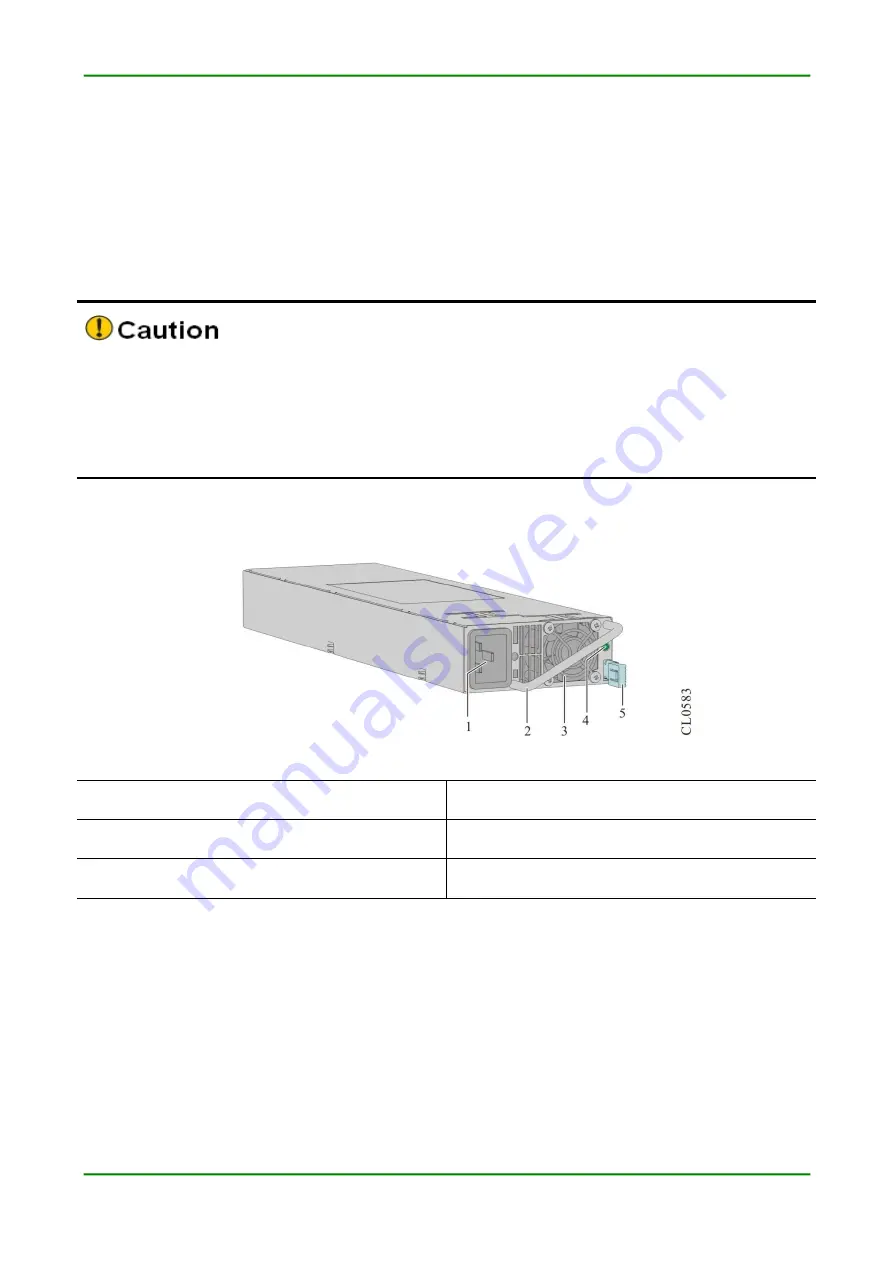
The appearance diagram of the AC power module is as follows:
Figure 1-7 The appearance diagram of the AC power module
1. AC power jack
2. Power handle
3. Power fan
4. Power status indicator
5. Power elastic snap
1.7 Fan Module and Device Air Passage
The fan module of S12800 routing switch is the important part of ensuring the normal running
of the device system (mandatory module), providing the air flow for the system dissipation. It
has the following functions and features:
Valid dissipation: Ensure that the device can run normally for a long time
Status monitoring: Support the fan faulty alarm


