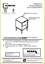
Mainstays GSB332199-2 Скачать руководство пользователя страница 1

TM

MAINSTAYS

Modern Nightstand

Stock # GSB332199-2

15-20minutes

approx assembly time

One adult

Assembly

THIS INSTRUCTION BOOKLET CONTAINS IMPORTANT SAFETY INFORMATION.

PLEASE READ AND KEEP FOR FUTURE REFERENCE.

For assistance with assembly or installation, parts and customer

service , call 1-888-568-3818 Monday-Friday 8:30am-5:30pm

PST (U.S)

Email: [email protected]

Working hour: Mon.-Fri., 8:30am - 5:30pm Pacific Standard

Time.

Stock # GSB332199-2

Lot Number : _________

Date Purchased ______/____/_____

Manufactured By : Young Chain Company Limited

Binh Duong Province, Vietnam

TEL : 1-888-568-3818

EMAIL : [email protected]

We are available to assist you Monday-Friday

From 8:30am-5:30pm PST (US)

MAXIMUM LOAD 44 LB (20 KG)

DRAWER MAXIMUM LOAD

 10 LB (4.54 KG)

Review your purchases, thank you!

Share your feedback to help other shoppers

Link for this product is as below:

www.walmart.com/ip/702434464

Содержание GSB332199-2

Страница 1: ...ice s goldenspecies com Working hour Mon Fri 8 30am 5 30pm Pacific Standard Time Stock GSB332199 2 Lot Number _________ Date Purchased ______ ____ _____ Manufactured By Young Chain Company Limited Bin...

Страница 2: ...embly The shipping box provides an ideal work surface To avoid accidentally discarding small parts or hardware do not dispose of any packaging or contents of the shipping carton until assembly is comp...

Страница 3: ...G H I J K LEFT SIDE PANEL 1 RIGHT SIDE PANEL 1 DRAWER FRONT PANEL 1 DRAWER LEFT PANEL 1 DRAWER RIGHT PANEL 1 DRAWER BACK PANEL 1 DRAWER BOTTOM PANEL 1 SIDE LEG 4 VERIFY THAT ALL PARTS ARE LISTED BEFOR...

Страница 4: ...L 16 1 BUCKLE 2 FLAT HEAD SCREW 4 1 STICKER PVC 12 1 2 3 4 1 6 7 8 5 VERIFY THAT ALL PARTS ARE LISTED BEFORE BEGINNING Page 4 HARDWARE LIST SHORT ROUND HEAD SCREW 4 1 LONG ROUND HEAD SCREW 16 1 TOOLS...

Страница 5: ...anel 4 Connect the previously tightened cam bolt with the panel connected into the cam lock 5 Using a flat head screw driver turn the cam lock halfway clockwise to secure the cam bolt 6 FAILURE TO PRO...

Страница 6: ...of the TOP A And use a hand screwdriver to tighten the CAM BOLT 1 clockwise Repeat these same steps for the BASE B ASSEMBLY Page 6 Please call for replacement parts or assistance 1 888 568 3818 Young...

Страница 7: ...ng up 2 Insert the CAM BOLT 1 into the corresponding hole of the LEFT SIDE PANEL C And use a hand screwdriver to tighten the CAM BOLT 1 clockwise Repeat these same steps for the RIGHT SIDE PANEL D ASS...

Страница 8: ...DOWEL 3 all the way into the corresponding hole of the LEFT SIDE PANEL C RIGHT SIDE PANEL D ASSEMBLY Page 8 Please call for replacement parts or assistance 1 888 568 3818 Young Chain Company Limited D...

Страница 9: ...Insert the DOWEL 3 all the way into the corresponding hole of the BACK PANEL E ASSEMBLY Page 9 Please call for replacement parts or assistance 1 888 568 3818 Young Chain Company Limited DOWEL 8 3 4...

Страница 10: ...s aligned with the cam bolt as the figure shown below 3 Use a hand screwdriver to turn the CAM LOCK 2 clockwise to secure the cam bolt ASSEMBLY Page 10 Please call for replacement parts or assistance...

Страница 11: ...to the corresponding hole the direction of the notch is aligned with the cam bolt as the figure shown below 4 Use a hand screwdriver to turn the CAM LOCK 2 clockwise to secure the cam bolt Page 11 6 P...

Страница 12: ...ole the direction of the notch of the cam locks align with the cam bolt 3 Use a hand screwdriver to turn the CAM LOCK 2 clockwise to secure the cam bolt Page 12 Please call for replacement parts or as...

Страница 13: ...hole the direction of the notch of the cam locks align with the cam bolt 3 Use a hand screwdriver to turn the CAM LOCK 2 clockwise to secure the cam bolt Page 13 Please call for replacement parts or a...

Страница 14: ...Chain Company Limited ASSEMBLY LONG ROUND HEAD SCREW 16 8 1 Use LONG ROUND HEAD SCREW 8 to attach the LEG F to the pilot holes on BASE B Repeat these steps for all the four legs Note Use the adjustabl...

Страница 15: ...The side with the holes should be facing up 2 Insert the CAM BOLT 1 into the corresponding hole of DRAWER FRONT PANEL G as shown in below figures 3 Use a hand screwdriver to tighten the CAM BOLT 1 cl...

Страница 16: ...he direction of the notch is aligned with the cam bolt as the figure shown below 3 Use a hand screwdriver to turn the CAM LOCK 2 clockwise to secure the cam bolt ASSEMBLY Please call for replacement p...

Страница 17: ...R BOTTOM PANEL K to the groove of DRAWER LEFT PANEL H and DRAWER RIGHT PANEL I All the way until into the groove of the DRAWER FRONT PANEL G ASSEMBLY Please call for replacement parts or assistance 1...

Страница 18: ...he FLAT HEAD SCREW 6 into the corresponding holes 3 Use a hand screwdriver to turn the FLAT HEAD SCREW 6 clockwise to secure the Drawer back panel ASSEMBLY Please call for replacement parts or assista...

Страница 19: ...e figure shown below 2 Cover any visible CAM LOCK 2 using STICKER 7 as shown below This buckle is optional use only when drawer bottom panel is not steady ASSEMBLY Please call for replacement parts or...

Страница 20: ...all the way and move ball bearing pieces to the front ends as figure shown below 3 Insert the pre assembled glides on the drawer side panels into the glides on the side panel and push in to assemble...

Страница 21: ...es a viernes de 8 30 a M A 5 30 p M Est ndar del Pac fico Hora Valores GSB332199 2 Numero de lote _________ Fecha de compra ______ ____ ____ Fabricado por Young Chain Company Limited Binh Duong Provin...

Страница 22: ...as incluidas No se recomienda el uso de herramientas el ctricas para el montaje Las herramientas el ctricas pueden da ar el hardware y o partir la madera Nota No apriete completamente todos los pernos...

Страница 23: ...LATERAL DERECHO 1 PANEL FRONTAL DEL CAJ N 1 PANEL IZQUIERDO DEL CAJ N 1 PANEL DERECHO DEL CAJ N 1 PANEL TRASERO DEL CAJ N 1 PANEL INFERIOR DEL CAJ N 1 PIERNA LATERAL 4 PANEL POSTERIOR 1 PARTES VERIFIQ...

Страница 24: ...NA TORNILLO 4 1 PEGATINA PVC 12 1 2 3 4 1 6 7 8 5 REDONDA CORTA TORNILLO DE CABEZA 4 1 RONDA LARGA TORNILLO DE CABEZA 16 1 LISTA DE HARDWARE VERIFIQUE QUE TODAS LAS PIEZAS EST N ENUMERADAS ANTES DE CO...

Страница 25: ...nillo m s grande de la leva debe tocar el panel 3 Inserte el seguro de leva en el orificio pretaladrado en el panel La flecha mira hacia el exterior del panel 4 Conecte el perno de leva previamente ap...

Страница 26: ...ador de mano para apretar el PERNO DE LEVA 1 en el sentido de las agujas del reloj Repita estos mismos pasos para la BASE B PERNO DE LEVA 12 1 MONTAJE P gina 6 Llame para solicitar piezas de repuesto...

Страница 27: ...PERNO DE LEVA 1 en el orificio correspondiente del PANEL LATERAL IZQUIERDO C Y use un destornillador de mano para apretar el PERNO DE LEVA 1 en el sentido de las agujas del reloj Repita estos mismos p...

Страница 28: ...ta el fondo en el orificio correspondiente del PANEL LATERAL IZQUIERDO C PANEL LATERAL DERECHO D CLAVIJA 8 3 3 MONTAJE P gina 8 Llame para solicitar piezas de repuesto o asistencia 1 888 568 3818 Youn...

Страница 29: ...la CLAVIJA 3 hasta el fondo en el orificio correspondiente del PANEL POSTERIOR E CLAVIJA 8 3 4 MONTAJE P gina 9 Llame para solicitar piezas de repuesto o asistencia 1 888 568 3818 Young Chain Company...

Страница 30: ...a en la figura a continuaci n 3 Utilice un destornillador de mano para girar el BLOQUEO DE LEVA 2 en el sentido de las agujas del reloj para asegurar el perno de leva BLOQUEO DE LEVA 2 2 5 C Aseg rese...

Страница 31: ...direcci n de la muesca est alineada con el perno de leva como se muestra en la figura a continuaci n 4 Utilice un destornillador de mano para girar el BLOQUEO DE LEVA 2 en el sentido de las agujas del...

Страница 32: ...sca de los bloqueos de leva se alinea con el perno de leva 3 Utilice un destornillador de mano para girar el BLOQUEO DE LEVA 2 en el sentido de las agujas del reloj para asegurar el perno de leva BLOQ...

Страница 33: ...ca de los bloqueos de leva se alinea con el perno de leva 3 Utilice un destornillador de mano para girar el BLOQUEO DE LEVA 2 en el sentido de las agujas del reloj para asegurar el perno de leva BLOQU...

Страница 34: ...LATERAL F a los orificios gu a de la BASE B Repita estos pasos para las cuatro patas Nota Utilice los niveladores ajustables para nivelar la mesa de noche moderna si es necesario 9 Niveladora MONTAJE...

Страница 35: ...be mirar hacia arriba 2 Inserte el PERNO DE LEVA 1 en el orificio correspondiente del PANEL FRONTAL DEL CAJ N G como se muestra en las figuras siguientes 3 Utilice un destornillador de mano para apret...

Страница 36: ...rno de leva como se muestra en la figura a continuaci n 3 Utilice un destornillador de mano para girar el BLOQUEO DE LEVA 2 en el sentido de las agujas del reloj para asegurar el perno de leva I BLOQU...

Страница 37: ...K en la ranura del PANEL IZQUIERDO DEL CAJ N H y el PANEL DERECHO DEL CAJ N I Todo el camino hasta la ranura del PANEL FRONTAL DEL CAJ N G MONTAJE Llame para solicitar piezas de repuesto o asistencia...

Страница 38: ...ientes 3 Utilice un destornillador de mano para girar el CABEZA PLANA TORNILLO 6 en el sentido de las agujas del reloj para asegurar el panel posterior del caj n CABEZA PLANA TORNILLO 4 6 J Aseg rese...

Страница 39: ...continuaci n 2 Cubra cualquier BLOQUEO DE LEVA visible 2 usando la PEGATINA PVC 7 como se muestra a continuaci n Esta hebilla es opcional sela solo cuando el panel inferior del caj n no est firme HEBI...

Страница 40: ...as piezas del rodamiento de bolas hacia los extremos frontales como se muestra en la figura a continuaci n 3 Inserte los rieles premontados de los paneles laterales del caj n en los rieles del panel l...

Отзывы: