


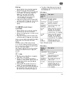
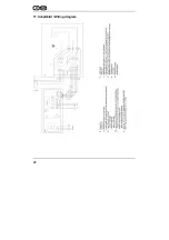
15
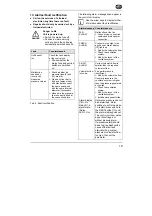
Installation preparations
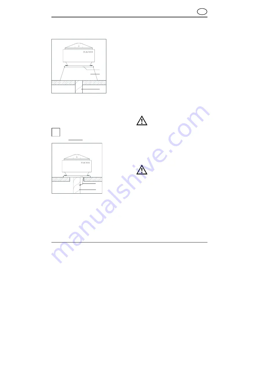
Install the ventilation ducts and roof socket
correctly.
52 Pressure line
53 Roof socket
54 Ventilation duct
If the exhaust air duct is connected directly to
the fan unit, install the supplied pressure
connection kit [27] (Art. no. 0093.0151.0000).
If the fan is fitted in combination with a
roof socket, the pressure connection
kit does not have to be installed.
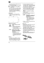
55 Ventilation duct
56 Pressure connection kit
Drill two Ø 2...2.5 mm holes in the
ventilation duct [26]. Screw in the pressure
connection kit plastic nipple [27] and
connect the compressed air hose.
The support surface for the GRD unit and
the control unit must be level.
Lay a permanent power cable to the
installation location.
Lay a permanent 6-core, shielded control
cable (diameter 0.25 to 0.34 mm²),
between the GRD unit and the control unit
installation location.
Installation tips
● Observe the planning documents drawn up
by the engineering office.
● Use appropriate insulation, sound-
deadening and installation material in the
area between the roof flashing [13] and
roof socket.
● If necessary, use Maico ELA.. flexible cuffs.
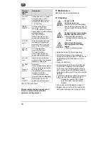
9. Assembly
GRD unit
DANGER
Danger to life caused by
inadequate mounting of the
roof fan.
The fixing points on the roof
socket must match up with the
4 drilled holes in the roof
flashing.
Provide mounting material of a
sufficient size (screws with
diameter of 10 mm, min.
strength class 8.8).
CAUTION
Risk of cuts from metal housing
plates with sharp edges.
Wear protective gloves.
Remove both ring nuts [2] and unit roof [1].
Remove the terminal box cover [7].
Feed the power and control cables into the
GRD terminal box [7] from below through
the empty ducting [11].
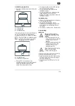
Carefully locate the GRD unit on the roof
socket.
6
2 5
2 6
2 7
2 6
i
GB