background image

ExpressCard 1000 Service Manual 

110 
 

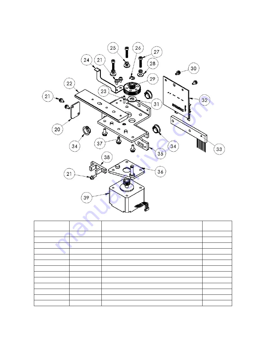
XY Carriage 


Assembly 

Index Part 

Number 

Description 

Quantity 


 33070277 

CARRIAGE,X-Y 

AXIS 


4-20 

33070107 

LOCK, Y-AXIS BELT CLAMP 

4-21 

46500027 

SCREW SEMS CONE WASH 4-40 X 1/4 

4-22 33070175 

BEARING, X AXIS LINEAR 

4-23 

46404001 

SOCKET SET SCREW 4-40 X 5/8 

4-24 

33070253 

FLAG,X- AXIS OPTO 

4-25 

48306000 

WASHER LOCK #6 (SPLIT) 

4-26 85800002 

RETAINING RING, E TYPE 3/16 SHAFT 

4-27 

46500150 

SCREW-METRIC M3 X .5  X 14 SOCKET HEX 

4-28 

48104000 

WASHER FLAT #4 

4-29 

33070414 

PM X-AXIS COMPOUND GEAR 

4-30 

46500027 

SCREW SEMS CONE WASH 4-40 X 1/4 

4-31 88600024 

WASHER,BRASS 

.26 

ID X .56 OD X .04 THK 


Содержание EXPRESSCARD 1000

Страница 1: ...00 HARDWARE SERVICE MANUAL MARCH 2008 Part Number 99875357 2 Registered to ISO 9001 2000 20725 South Annalee Avenue Carson CA 90746 Phone 310 631 8602 Fax 310 631 3956 Technical Support 651 415 6800 w...

Страница 2: ......

Страница 3: ...nical for any purpose without the express written permission of MagTek Inc Copyright 2007 2008 MagTek is a registered trademark of MagTek Inc ExpressCard 1000 is a trademark of MagTek Inc MagnePrint i...

Страница 4: ...7 Security 19 2 8 Changing Default Password 22 Section 3 Service Procedures 23 3 1 Tools and Materials 23 3 2 Handling ESD Sensitive Parts 24 3 3 Maintenance 25 Lubrication 25 Print Head Cleaning 25...

Страница 5: ...9 Monitor Replacement 83 Section 5 Parts Catalog 87 5 1 Covers Assembly 88 Top Cover 89 Front Cover with Display 90 Left Cover 91 Left Top Cover Latch Assembly 92 Right Cover 93 Right Top Cover Latch...

Страница 6: ...v 5 6 Printer Assembly 122 5 7 Sliding Tray Assembly 123 Section 6 Cabling Diagram Index 125 Appendix A 185 Acronyms 185 Accessory Items 186 Optional Components 186 Supplies 186 Technical Support 186...

Страница 7: ...lowing two conditions 1 this device may not cause harmful interference And 2 this device must accept any interference received including interference that may cause undesired operation CANADIAN DOC ST...

Страница 8: ...tended for general use To maintain the safety and integrity of the machine it is essential that procedures laid out within this manual are followed CAUTION Disconnect power from the ExpressCard 1000 E...

Страница 9: ...ExpressCard 1000 Hardware Service Manual 2...

Страница 10: ...odate network requirements for further details refer to the EC1000 software manual Dimensions Length 24 25in Height 15 13in Width 26 77in Weight 80lbs Magnetic Stripe Encoding MSR Read data Format Spe...

Страница 11: ...d PVC finish monochrome resin required for 100 polyester cards optical memory cards with PVC finish Accepted Card Compositions PVC or polyester cards with polished PVC finish monochrome resin required...

Страница 12: ...t speeds do not include the time needed for the PC to process the image Process time is dependent on the size of the file the CPU amount of RAM and the amount of available resources at the time of the...

Страница 13: ...ExpressCard 1000 Hardware Service Manual 6...

Страница 14: ...d to open electronic locks on the cover 4 Open the Print head assembly by gently pulling up on the assembly s release tab and lifting upwards This will allow the assembly to swing completely open 5 Pl...

Страница 15: ...ou start to print the ribbon drive hubs will automatically engage the notches on both cores of the ribbon roll Note If the printer has difficulty recognizing the installed ribbon a calibration of the...

Страница 16: ...ch you intend to print Oil or dirt from the hands can impair print quality Handle cards only along the edges 3 Load the stack of cards into the EC1000 card input tray and pushing the stacks all the wa...

Страница 17: ...s normal operation When the system displays Offline it will not process a card In addition to determine the firmware version on the machine select the Help button and it will be displayed The menu scr...

Страница 18: ...btain an IP address automatically however for most networks the IP address must be statically set To configure the network interface on the EC1000 follow the steps below to configure the network card...

Страница 19: ...words must be entered on the screen shown 4 Once the correct passwords have been entered the screen below will be displayed At this point enter the IP address gateway and subnet of the network you are...

Страница 20: ...figuring the IP address then the error below will be shown 5 After the network configuration has been entered shown below press the set new button on the screen the network card configuration is now c...

Страница 21: ...Calibration of the printer ribbon is normally not required however if the ribbon is not recognized automatically follow the calibration instructions below 1 Select Menu from the system ready screen 2...

Страница 22: ...Section 2 Installation Operation 15 3 Next select the Properties button 4 Select Printing Preferences...

Страница 23: ...ExpressCard 1000 Service Manual 16 5 Then select the Calibrate tab 6 Now select Sensors...

Страница 24: ...er will begin its calibration cycle During the printer calibration cycle you will hear noise from the printer when the printer is silent select Ok twice on the next two screens 8 The screen below shou...

Страница 25: ...properly To print a test card press the Samples button at the system ready screen and four sample options will appear as shown below Select the sample type you wish to create and a card will be emboss...

Страница 26: ...rators will need to follow the steps below From the system ready screen select Menu Case Door and then enter the required user password by default the password is 1 2 3 2 5 8 0 Once the password has b...

Страница 27: ...ExpressCard 1000 Service Manual 20 Main Menu screen Password screen...

Страница 28: ...assis The anchor hole is on the right side of the machine and visible through the access opening on the upper chassis next to the exit assembly Once the anchor hole has been located a lag bolt or some...

Страница 29: ...reen below will be shown At this point select the password that you would like to change Password must be between 7 to 16 characters long Note If a password has been lost or forgotten the password can...

Страница 30: ...rror repair or replace the defective part or sub assembly 3 1 Tools and Materials Required tools Flat blade screwdrivers various sizes long and short Phillips screwdrivers set 6 and 12 Nut driver set...

Страница 31: ...scharge Static charges increase as a result of clothing fibers carpets and furniture etc Use an ESD wrist strap connect to a ground point the chassis This will discharge any static electricity from yo...

Страница 32: ...Open the EC1000 s top cover and then open up the print head assembly 2 Use a Print head Cleaning Pen from the Printer Cleaning Kit firmly wipe back and forth across the surface of the print head 3 On...

Страница 33: ...een use step three to navigate to screen to move the Platen Roller back and forth while cleaning 9 After the Platen Roller is clean and completely dry replace the printing supplies and close the print...

Страница 34: ...the Ready screen then select the Load F W button that is shown below After the Load F W button is selected you will see the screen below At this point select the appropriate file in the box to the lef...

Страница 35: ...telliCat manuals p n 99875362 and p n 99875347 Updates via the Internet MagTek provides software and firmware updates for the EC1000 through the internet to update the EC1000 s software follow the ins...

Страница 36: ...Section 3 Service Procedures 29 2 Click the browse button and find the package MTECUPDATE CAB 3 Click the send button A message will indicate the status of the upload 4 Restart the EC1000...

Страница 37: ...rd 1000 Service Manual 30 5 Access the EC1000 webpage again and select Upload Status again in the gray field to the left of the page 6 A successful upload will be indicated with a status of SUCCESS sh...

Страница 38: ...hown below Note If the machine has already been activated the Activation button will not respond After pressing the Activation button the screen below will be shown and unique challenge code will be d...

Страница 39: ...shown below Then press the Status button to return to the system ready screen To check the activation status select the help button from the Ready screen and the screen below will be shown In the scre...

Страница 40: ...ght on the XY clamp rail 3 Parameter that controls this distance is PrinterHandoffAdjustmentY When this parameter is increased the XY clamp will move in closer to the spring loaded aluminum rail refer...

Страница 41: ...you to determine where the XY assembly will start and stop its movement so that it can pick and drop the card in the correct position To adjust the position follow the steps below 1 Press the Menu but...

Страница 42: ...of the printer hand off position is generally a trial and error process When a value is increased the XY clamp will move in closer to the spring loaded aluminum rail and when the value is decreased i...

Страница 43: ...mbossed characters align properly with the printed characters To adjust the embossed characters positions follow the steps below Note The EC1000 should be re tuned during periodic maintenance and re t...

Страница 44: ...ine that are equipped with Visa Electron or American Express fonts Once a parameter has been selected the characters on the displayed card will be highlighted in blue and position will be indicated by...

Страница 45: ...button the screen below will then appear With the regular tuning screen all fonts move relative to one another however the Advanced function screen allows independent adjustment of the FontID charact...

Страница 46: ...aracters of the name Increasing the CardOffsetX value will move the embossed characters to the right and decreasing the CardOffsetY will move the embossed characters down If the position of the emboss...

Страница 47: ...mpleted the embossed characters should be perfectly aligned and your sample card should look like the figure below The guide below should be useful when making adjustments to the embossing printing po...

Страница 48: ...assigned to a different hopper Adjust X_SPI value and FontID2 Spacing value until the end of the FontID2 name and expiration dates embossed character and printed character are properly align Sample 1...

Страница 49: ...follower may be required to ensure that embossed characters are at the proper height on the card To adjust of the follower refer to the instructions on the next page Note Adjustment of the hammer fol...

Страница 50: ...r Hammer Follower 1 Determine and save the original Hammer follower setting before changing the value for future reference Refer to figures 2 and 3 for Hammer Follower settings Figure 1 Figure 2 Top H...

Страница 51: ...igure 3 Hammer Follower Height Indicators Lighter impression Deeper impression The Low to High adjustment is a reference mark on the Hammer Follower edge which indicates the pressure height of the cur...

Страница 52: ...n in figure Manufacture specification Minimum height 0 018in 0 46mm Maximum height 0 019in 0 48mm For more specification information refer to section 1 3 Note When measuring the embossed character hei...

Страница 53: ...is utility navigate to the main Menu screen and select the Font Editing button Once this function is selected you will be prompted for the user passwords After properly entering the passwords the Font...

Страница 54: ...Menu button and select samples to print a test card If the card is bowed up or down refer to the diagrams below To reduce the bowing in the card reduce the hammer depth on which ever direction the ca...

Страница 55: ...hopper with arrow face up and pointing into the machine 3 The card access door is shut the machine will not run if open 4 The Ethernet or crossover cable is connected and there is a good connection 5...

Страница 56: ...e running open the top cover and block the sensor located on the right rear portion of the top cover track If you would like to isolate an assembly for troubleshooting this can be done from the menu s...

Страница 57: ...he image below If you suspect that a sensor is faulty block open the sensor and the display will change to red or green XY Mover Selecting the XY Mover button from the Menu screen will allow you to ma...

Страница 58: ...also predefined steps that are shown below When you have completed your tests make sure that the top and bottom clamps are open or the wheel will jam MCP Commands The MagTek Command Protocol MCP Utili...

Страница 59: ...ExpressCard 1000 Service Manual 52 First from the pull down menu select the type of function you wish to conduct Next select the motor that you want to test from the pull down menu...

Страница 60: ...cedures 53 If a sensor is needed for the testing purposes select it and press the Send Cmd button to run the test After the test has been completed make sure to press the Stop button or the machine wi...

Страница 61: ...he rear of the printer and the motherboard Error Encode Verify This indicates that the data encoded to the card could not be verified when the card was read Please ensure that the card stock is correc...

Страница 62: ...nforms to the text requirements of the printer Error XY Move To Eject Handoff Position This indicates that there was a difficulty in the XY Transport moving the card to the final stage card eject Chec...

Страница 63: ...ExpressCard 1000 Service Manual 56...

Страница 64: ...e removal instructions When replacing components be sure to follow the previously stated ESD procedures section 3 2 and common safety practices 4 1 Covers Replacement time 45 minutes 1 Disconnect the...

Страница 65: ...pressCard 1000 Service Manual 58 3 Disconnect the top and side latch solenoids from the XY break out board 4 Disconnect the top cover and card access door sensors from the exit transport break out boa...

Страница 66: ...ver screws located on the upper rear portion of the chassis shown below Hint hold the top cover as you remove these screws the top can fall off easily when the screws are removed 6 Remove the top cove...

Страница 67: ...four per side and the two front screws shown below Hint applying a little pressure to the outside cover will make it easier to remove and replace the screws Note you must open the card access door to...

Страница 68: ...en the electronics access door via the thumb screws shown and disconnect the monitor video USB and power cables 9 Slowly lift the remaining covers off the chassis while pulling the video cables throug...

Страница 69: ...minutes after covers have been removed 1 Disconnect the power and data cables 2 Remove the outer covers refer to section 4 1 for instructions 3 Cut the zip ties on the ribbon and power cables 4 Discon...

Страница 70: ...bility and carefully place the Allen wrench between the tines to gain access to the screws Note when reinstalling the embosser assembly align the square and round cut out on the assembly base with the...

Страница 71: ...ly Replacement time 30 minutes after covers are removed 1 Disconnect the power and data cables 2 Remove the outer covers optional refer to section 4 1 for instructions 3 Disconnect the ribbon and powe...

Страница 72: ...wire to the top deck 5 Grasp the XY assembly from the opposing black ends and lift away from the top deck 6 After the replacement process is completed verify that the print emboss alignment is in the...

Страница 73: ...Exit Assembly Replacement time 25 minutes 1 Disconnect the power and data cables 2 Remove the four screws that hold the break out board in place in the exit assembly 3 Once the screws have been remov...

Страница 74: ...portion must be securely attached to the top desk first After the Eject Slide is mounted the Exit Transport portion needs to be positioned using slotted screw holes next to the Eject Slide However th...

Страница 75: ...n 4 3 for instructions optional 5 Remove the Exit assembly refer to section 4 4 for instructions optional 6 Disconnect the justifier sensor from the XY break out board 7 Remove the four Allen screws 5...

Страница 76: ...the top deck to place the printer in the correct position this will assure proper alignment 10 Next disconnect the power and USB cables to the printer and the I380 encoder module Note when the new pri...

Страница 77: ...Printhead Assembly Locate the value labeled R XXXX the average resistance value of the Printhead Example R 3400 Write the R value down for reference 3 To remove the Original Printhead Assembly follow...

Страница 78: ...sistent with the overall position and darkness of the test print from the old Printhead the Printhead installation is complete If you notice a problem with the test print please review the troubleshoo...

Страница 79: ...sample shown below go to Step 5 to adjust the Print TOF 5 Decrease the Print TOF value to move the printed image more toward the leading edge of the card OR Increase the Print TOF value to move the p...

Страница 80: ...look like the sample shown below go to Print EOF 4 Decrease the Print EOF value to move the printed image more toward the leading edge of the card OR Increase the Print EOF value to move the printed i...

Страница 81: ...the printed image Caution Be sure to make adjustments in small increments of 4 to avoid over adjusting this setting The Ribbon can jam or break if the setting is too high 6 Press DONE to save the valu...

Страница 82: ...t the power and data cables 2 To open the Sliding Tray access door open the EC1000 the top cover and unscrewing the two thumb screws located on the top deck next to the embosser and XY assemblies 3 On...

Страница 83: ...rt and Eject Slide shown below 5 Unscrew the thumb screw located just inside Sliding Tray access door way on the front side portion of the tray 6 Place your fingers in the hole on opposite sides of th...

Страница 84: ...ables and power cables for the XY assemble and the embosser These connectors are located on the front right side of the MLB board shown below 8 Slowly pull the tray forward again until the back MSR ra...

Страница 85: ...ll cables within the EC1000 are labeled by name and the corresponding board connector number 10 Now that the MLB cables have been disconnected slowly pull the tray out of the chassis and you are able...

Страница 86: ...n move the tray to a suitable where components can be replaced if needed The picture below identifies the components that make up the electronics tray When reinstalling the tray reverse the removal in...

Страница 87: ...ExpressCard 1000 Service Manual 80...

Страница 88: ...s from the top on the power supply 3 Then position the right side of the EC1000 side with the power supply over the end of a table and remove the two the Phillip screws that secure the power supply to...

Страница 89: ...ent time 10 minutes To replace the MSR rail remove the three screws shown below and slowly pull the rail away from the front cover When the MSR board becomes accessible disconnect the MSR cable and re...

Страница 90: ...ables 2 Remove the outer cover assemble refer to section 4 1 for instructions 3 After removing the cover assemble place the assembly on a table top monitor side down as shown in the figure below 4 Rem...

Страница 91: ...o remove the nut plate which is in the channel on the rear of the monitor To reassemble the monitor bracket simply follow the step in reverse Note when attaching the monitor and bracket to the cover a...

Страница 92: ...using key or open before disconnecting power disconnect the monitor video cable and remove the four screws that secure the monitor bracket to the cover assembly 3 After removing the securing screws li...

Страница 93: ...ExpressCard 1000 Service Manual 86...

Страница 94: ...87 Section 5 Parts Catalog Assembly 5 1 Covers Assembly 5 2 Chassis Assembly 5 3 Embosser Assembly 5 4 X Y Transport Assembly 5 5 Exit Transport Assembly 5 6 Printer Assembly 5 7 Sliding Tray...

Страница 95: ...ExpressCard 1000 Service Manual 88 5 1 Covers Assembly...

Страница 96: ...NE WASH 6 32 X 3 8 5 1 3 33070297 TOP COVER FRONT 1 1 4 33070377 PIN HINGE COVER 2 1 5 85600135 BEARING FLANGED 188 ID X 25 OD X 25 LG 6 1 6 33070390 LABEL EC1000 MAGTEK LOGO 1 1 7 33070298 TOP COVER...

Страница 97: ...000 1 1 14 93600157 EC 1000 8 LCD TOUCH SCREEN SIL 1 1 15 33070392 ASSY HEAD AND RAIL 1 1 16 46500040 SCREW SEMS CONE WASH 6 32 X 3 8 9 1 17 33070379 PLATE NUT LCD MOUNTING 1 1 18 33070378 BRACKET LCD...

Страница 98: ...Index Part Number Description Quantity 33070367 ASSY COVER LFT SIDE W LATCH 1 23 33070296 LEFT SIDE COVER EC1000 1 1 24 33070381 ASSY SOLENOID TOP RIGHT LATCH 1 1 25 33070421 PLATE NUT HALF LENGTH 2 1...

Страница 99: ...5106003 SCREW PAN HD PHIL 6 32x3 16 1 1 30 88300196 COMP SPRING 375 OD X 020WRE X 1 LG 2 1 31 85800004 RETAINING RING E TYPE 3 32 SHAFT 2 1 32 85800003 RETAINING RING E TYPE 1 8 SHAFT 1 1 33 33070470...

Страница 100: ...CBL PANEL DOOR OPEN SENSOR 30 1 1 42 33070471 TOP COVER SENSOR BRACKET 1 1 43 33070295 RIGHT SIDE COVER EC1000 1 1 44 33070299 ACCESS DOOR EC1000 1 1 45 33070361 CLEAR WINDOW ACCESS DOOR 1 1 46 330703...

Страница 101: ...33070437 LATCH DOG LEG 1 1 54 33070501 LATCH SPACER 1 1 55 33070372 PLATE MOUNTING SOLENOID RIGHT 1 1 56 45106003 SCREW PAN HD PHIL 6 32x3 16 3 1 57 85300032 SOLENOID LINEAR 24V 1 1 58 88300196 COMP...

Страница 102: ...H 1 64 33070385 LATCH SLIDER DOOR 1 1 65 33070470 SHAFT 3 32 DIA X 75L 1 1 66 85800004 RETAINING RING E TYPE 3 32 SHAFT 2 1 67 33070386 BRACKET SOLENOID DOOR 1 1 68 88300196 COMP SPRING 375 OD X 020WR...

Страница 103: ...ExpressCard 1000 Service Manual 96 5 2 Chassis Assembly...

Страница 104: ...rt Number Description Quantity 2 1 33070300 BASE EC1000 1 2 2 33070359 DOOR PCB ACCESS 1 2 3 46500039 SCREW SEMS CONE WASH 6 32 X 5 16 17 2 4 33070301 TOP DECK EC1000 1 2 5 64300106 PWR EC1000 PS 115...

Страница 105: ...1 2 11 46500028 SCREW SEMS CONE WASH 6 32 X 1 4 3 2 12 33070424 RAIL SLIDING TRAY SHORT 1 2 13 33070488 0 5 HEX STANDOFF FM FM 1 4 20 2 160 LG 2 2 14 33070408 SLEEVE ACHOR BOLT 1 2 15 88500027 HEX WIT...

Страница 106: ...HEX WITH TOOTH WASHER 8 32 8 2 23 33070405 PSY CBL PC ETHERNET CABLE 28 5 1 2 24 88500026 LOCK NUT 1 4 20 SS NYLON INSERT 1 2 25 48325000 WASHER SPRING LOCK 1 4 1 2 26 77500013 CON MODULE AC INPUT SW...

Страница 107: ...l 100 5 3 Embosser Assembly Note There are three possible font configurations of the embosser assembly If the configuration is not known when ordering a replacement embosser verify the configuration b...

Страница 108: ...33070255 CHASSIS EMBOSSER 1 3 3 85600138 BEARING 251 IDX 316 ODX 25 LG 437 FL 1 3 4 33070085 PUNCH HAMMER EMBOSSER 1 3 5 33070419 PIN DOWEL ROCKER ARM 3 8 DIA X 1 75 LG W FLAT 1 3 6 33070262 ROCKER AR...

Страница 109: ...33070315 CAM BOTTOM HOME SENSOR 3 2 3 16 33070360 BRACKET SENSOR EMBOSSER 1 3 17 86100057 STANDOFF 1 4 OD ROUND X 1 0 LG 6 32 X 25 1 3 18 33070400 HOLDER PCB TOP 1 3 19 33090038 ASM EC1K EMBOSSER STE...

Страница 110: ...cription Quantity 3 26 33070052 GEAR EMBOSSER C AXIS RING 2 3 27 CONTACT HELP DESK FOR SPECIFIC CHARACTER PART NUMBER N A 3 28 33070427 SPRING WAVE 2 93 IDX 3 38ODX 275 FREE HT 1 3 29 86600079 DOWEL P...

Страница 111: ...70481 PUNCH HAMMER BEARING 1 3 35 86100057 STANDOFF 1 4 OD ROUND X 1 0 LG 6 32 X 25 1 3 36 46500151 SCREW SOCKET HD CAP 6 32 X 3 8 2 3 37 48306000 WASHER LOCK 6 SPLIT 2 3 38 85600138 BEARING 251 IDX 3...

Страница 112: ...46500095 SCREW BUTTON HD SKT CAP 4 40 X 3 16 4 3 47 64900044 STEPPER MOTOR 24V 2 8A PHASE EC1000 1 3 48 33070255 CHASSIS EMBOSSER 1 3 49 48306000 WASHER LOCK 6 SPLIT 2 3 50 86100057 STANDOFF 1 4 OD RO...

Страница 113: ...46500018 SCREW SOCKET HD CAP 6 32 X 1 2 1 3 58 48106000 WASHER FLAT 6 1 3 59 48300002 WASHER EXT TOOTH LOCK 6 SCREW 9 16 1 3 60 46500055 SCREW SEMS CONE WASHER 4 40 X 3 8 6 3 61 52300815 PHO SWITCH O...

Страница 114: ...Section 5 Parts Catalog 107 5 4 X Y Transport Assembly...

Страница 115: ...TE XY AXIS END 2 4 4 33070169 SPOOL BELT TENSION 1 4 5 85600066 BUSHING FLANGED 187 ID X 250 LG 2 4 6 33070428 PULLEY Y AXIS 1 4 7 48100003 WASHER SS 192 ID X 50 OD X 063 THK 2 4 8 85800021 RETAINING...

Страница 116: ...Part Number Description Quantity 4 14 48104000 WASHER FLAT 4 4 4 15 33070258 BRACKET Y AXIS MOTOR MOUNT 1 4 16 33070178 SHAFT Y AXIS MOTOR 1 4 17 33070413 PM X TRANSFER GEAR 1 4 18 64900037 MOTOR STEP...

Страница 117: ...3070175 BEARING X AXIS LINEAR 1 4 23 46404001 SOCKET SET SCREW 4 40 X 5 8 1 4 24 33070253 FLAG X AXIS OPTO 1 4 25 48306000 WASHER LOCK 6 SPLIT 4 4 26 85800002 RETAINING RING E TYPE 3 16 SHAFT 1 4 27 4...

Страница 118: ...T BOARD 1 4 33 33070506 XY STATIC BRUSH 1 4 34 85600126 BEARING SNAP IN THRUST NYLON 3 8 ID X 7 16 OD 3 4 35 33070259 CARRIAGE Y AXIS 1 4 36 33070285 MOUNT X AXIS MOTOR 1 4 37 46500040 SCREW SEMS CONE...

Страница 119: ...PHIL 4 40x3 4 2 4 43 33070274 HUB FLAG CLAMP MOTOR 1 4 44 86400027 SPACER NYLON 187ID X 343 OD X 110THK 2 4 45 33070103 LINK COMPLIANT 1 4 46 85800002 RETAINING RING E TYPE 3 16 SHAFT 1 4 47 33070409...

Страница 120: ...L X CARD CLAMP HARNESS 1 4 57 47104000 NUT HEX 4 40 2 4 58 33070256 JAW CARD CLAMP RHS 1 4 59 33070257 JAW CARD CLAMP LHS 1 4 60 48104000 WASHER FLAT 4 2 4 61 45104003 SCREW PAN HD PHIL 4 40 X 3 16 2...

Страница 121: ...ExpressCard 1000 Service Manual 114 5 5 Exit Transport Assembly...

Страница 122: ...2 SLIDER RIGHT SIDE 1 5 3 33070502 FAN MOUNT EJECT SLIDE 1 5 4 33070443 CARD EXIT SLIDE 1 5 5 33070466 EJECT BIN SEN EXIT FANS PATCH 2 CABLE 1 5 6 46500027 SCREW SEMS CONE WASH 4 40 X 1 4 4 5 7 330704...

Страница 123: ...SPORT ASSEMBLY 5 11 33070446 LEFT SIDE WALL 1 5 12 33070341 CBL REJECT BIN SENSOR 5 1 5 13 33090045 ASM EC1K EXIT EJECT XPORT BOARD 1 5 14 46500027 SCREW SEMS CONE WASH 4 40 X 1 4 5 5 15 45106010 SCRE...

Страница 124: ...art Number Description Quantity 5 18 88300195 TORSION SPRING 255 ID X 355 OD 1 5 19 85600139 FLANGE BEARING 188 ID X 25 3 5 20 46500039 SCREW SEMS CONE WASH 6 32 X 5 16 3 5 21 46500055 SCREW SEMS CONE...

Страница 125: ...0055 SCREW SEMS CONE WASHER 4 40 X 3 8 6 5 26 86400038 SPC SPACER NYLON 25 OD X 15 32 1 5 27 45106010 SCREW PAN HD PHIL 6 32 X 5 8 1 5 28 88300195 TORSION SPRING 255 ID X 355 OD 1 5 29 33070469 PULLEY...

Страница 126: ...ETH 1 5 36 46500056 SCREW SEMS CONE WASH 4 40 X 1 2 1 5 37 48106000 WASHER FLAT 6 1 5 38 48308002 WASHER EXT TOOTH LOCK WASHER FOR 8 SCREW 2 5 39 48100002 WASHER FLAT 13 64 ID X 11 16 OD X 033 3 5 40...

Страница 127: ...SPACER EJECT AXIS 4 5 47 33070509 ASSY BACK UP WHEEL EXIT TRANSPORT 3 5 48 33070473 LEFT ENTRY RAIL EXIT TRANSPORT 1 5 49 33070508 ASSY DRIVE WHEEL EXIT TRANSPORT 3 5 50 33070472 RAIL RIGHT ENTRY RAIL...

Страница 128: ...INEAR 24V 1 5 56 46500028 SCREW SEMS CONE WASH 6 32 X 1 4 2 5 57 66300012 FAN DC24V 6W 50MM X 50MM X 15MM 1 5 58 46500055 SCREW SEMS CONE WASHER 4 40 X 3 8 4 5 59 46500027 SCREW SEMS CONE WASH 4 40 X...

Страница 129: ...rt Number Description Quantity 33070270 FARGO PRINTER WITH I 380 6 1 33070280 PRINTER FARGO 1 6 2 33070269 I 380 WITH MAGNEPRINT EC1000 1 6 3 33070177 BRACKET FARGO CARD JUSTIFIER 1 6 4 46500152 BRACK...

Страница 130: ...TING TRAY 1 7 2 46500039 SCREW SEMS CONE WASH 6 32 X 5 16 13 7 3 64300109 POWER SUPPLY 400W 1 7 4 93600151 GENERIC HARDDRIVE 40GB SATA 7 4 33070504 HARD DRIVE W PRE LOADED SFTWR 1 7 5 33090032 PCB ASS...

Страница 131: ...ExpressCard 1000 Service Manual 124...

Страница 132: ...5 173 Power Module Harness 33070484 174 Assembly 3 Embosser Top Description Part Number Page Top Embosser MLB Power 33070305 129 Top Embosser MLB Ribbon 33070306 130 Z1 Stepper 33070307 129 Wheel Step...

Страница 133: ...art Number Page Exit Eject MLB Power 33070329 152 Exit Eject MLB Ribbon 33070330 153 Exit Motor 33070331 154 Top Case Open Det Sensor 33070338 155 Panel Door Open Det Sensor 33070340 156 Reject Bin Se...

Страница 134: ...age I 380 Serial Comm Port Extension cable 33070522 180 Assembly 6 Printer EC1000 Cabling Description Part Number Page Cover Solenoids Cable 33070320 181 Access Door Solenoid Cable 33070321 182 Access...

Страница 135: ...ExpressCard 1000 Hardware Service Manual 128...

Страница 136: ...Section 6 Cabling Diagram Index 129...

Страница 137: ...ExpressCard 1000 Hardware Service Manual 130...

Страница 138: ...Section 6 Cabling Diagram Index 131...

Страница 139: ...ExpressCard 1000 Hardware Service Manual 132...

Страница 140: ...Section 6 Cabling Diagram Index 133...

Страница 141: ...ExpressCard 1000 Hardware Service Manual 134...

Страница 142: ...Section 6 Cabling Diagram Index 135...

Страница 143: ...ExpressCard 1000 Hardware Service Manual 136...

Страница 144: ...Section 6 Cabling Diagram Index 137...

Страница 145: ...ExpressCard 1000 Hardware Service Manual 138...

Страница 146: ...Section 6 Cabling Diagram Index 139...

Страница 147: ...ExpressCard 1000 Hardware Service Manual 140...

Страница 148: ...Section 6 Cabling Diagram Index 141...

Страница 149: ...ExpressCard 1000 Hardware Service Manual 142...

Страница 150: ...Section 6 Cabling Diagram Index 143...

Страница 151: ...ExpressCard 1000 Hardware Service Manual 144...

Страница 152: ...Section 6 Cabling Diagram Index 145...

Страница 153: ...ExpressCard 1000 Hardware Service Manual 146...

Страница 154: ...Section 6 Cabling Diagram Index 147...

Страница 155: ...ExpressCard 1000 Hardware Service Manual 148...

Страница 156: ...Section 6 Cabling Diagram Index 149...

Страница 157: ...ExpressCard 1000 Hardware Service Manual 150...

Страница 158: ...Section 6 Cabling Diagram Index 151...

Страница 159: ...ExpressCard 1000 Hardware Service Manual 152...

Страница 160: ...Section 6 Cabling Diagram Index 153...

Страница 161: ...ExpressCard 1000 Hardware Service Manual 154...

Страница 162: ...Section 6 Cabling Diagram Index 155...

Страница 163: ...ExpressCard 1000 Hardware Service Manual 156...

Страница 164: ...Section 6 Cabling Diagram Index 157...

Страница 165: ...ExpressCard 1000 Hardware Service Manual 158...

Страница 166: ...Section 6 Cabling Diagram Index 159...

Страница 167: ...ExpressCard 1000 Hardware Service Manual 160...

Страница 168: ...Section 6 Cabling Diagram Index 161...

Страница 169: ...ExpressCard 1000 Hardware Service Manual 162...

Страница 170: ...Section 6 Cabling Diagram Index 163...

Страница 171: ...ExpressCard 1000 Hardware Service Manual 164...

Страница 172: ...Section 6 Cabling Diagram Index 165...

Страница 173: ...ExpressCard 1000 Hardware Service Manual 166...

Страница 174: ...Section 6 Cabling Diagram Index 167...

Страница 175: ...ExpressCard 1000 Hardware Service Manual 168...

Страница 176: ...Section 6 Cabling Diagram Index 169...

Страница 177: ...ExpressCard 1000 Hardware Service Manual 170...

Страница 178: ...Section 6 Cabling Diagram Index 171...

Страница 179: ...ExpressCard 1000 Hardware Service Manual 172...

Страница 180: ...Section 6 Cabling Diagram Index 173...

Страница 181: ...ExpressCard 1000 Hardware Service Manual 174...

Страница 182: ...Section 6 Cabling Diagram Index 175...

Страница 183: ...ExpressCard 1000 Hardware Service Manual 176...

Страница 184: ...Section 6 Cabling Diagram Index 177...

Страница 185: ...ExpressCard 1000 Hardware Service Manual 178...

Страница 186: ...Section 6 Cabling Diagram Index 179...

Страница 187: ...ExpressCard 1000 Hardware Service Manual 180...

Страница 188: ...Section 6 Cabling Diagram Index 181...

Страница 189: ...ExpressCard 1000 Hardware Service Manual 182...

Страница 190: ...Section 6 Cabling Diagram Index 183...

Страница 191: ...ExpressCard 1000 Hardware Service Manual 184...

Страница 192: ...used in reference to the application of preference to items printed on the card those using the black panel in lieu of a process YMC black YMCKO The designation of colored Ribbon by the panels of col...

Страница 193: ...93400023 1 silver ribbon p n 93400022 1 Cleaning card p n 96700020 Supplies One standard color ribbon will produce 400 cards when printing one side and 250 cards when printing on both sides p n 93400...

Страница 194: ...Appendix A 187 Notes...

Отзывы: