background image


8

ASSEMBLY INSTRUCTION: 

 
STEP 1-1. 

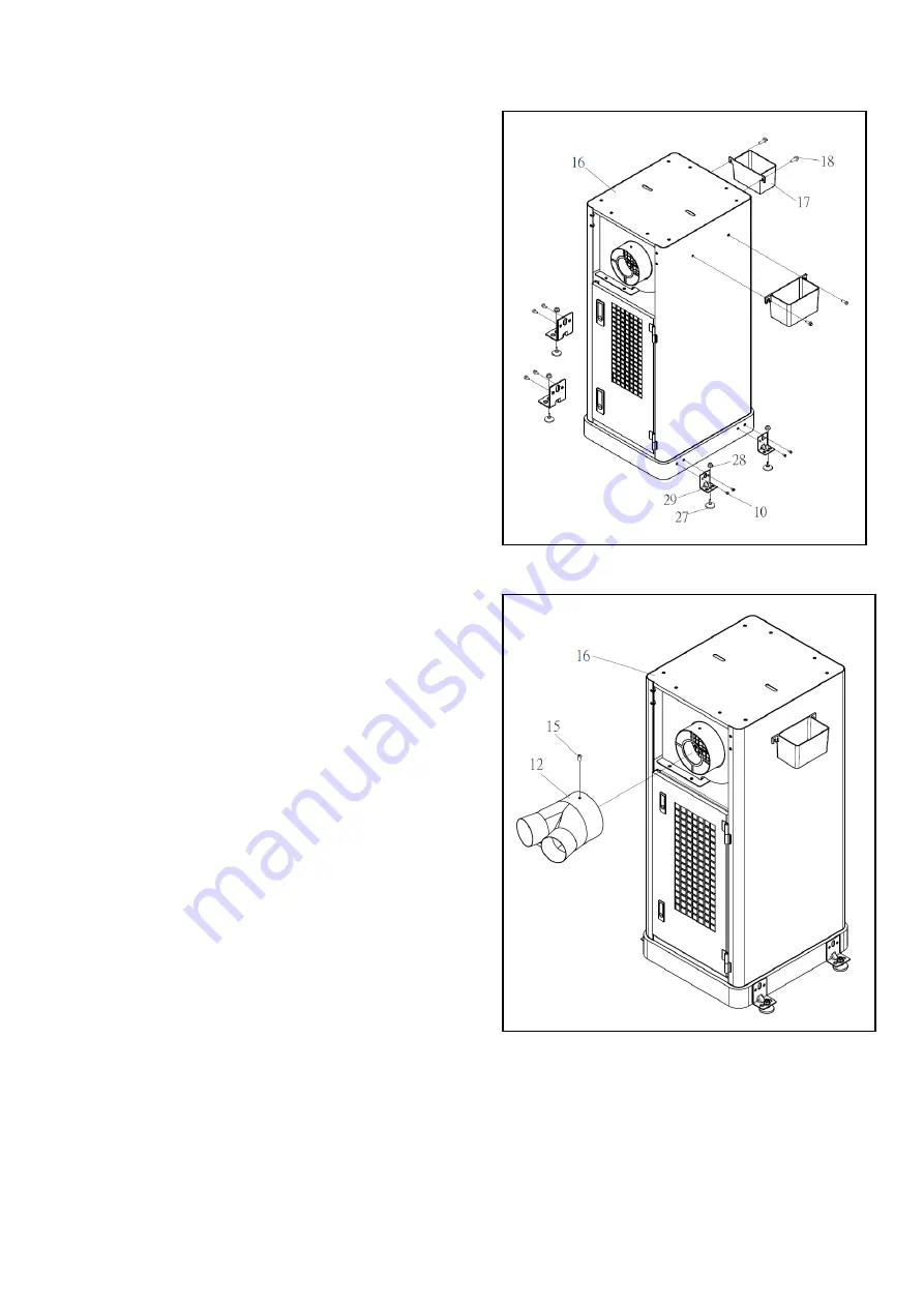
Assemble the fixing pad (NO. 29) on the main body   
(NO. 16) with hex flange screw (NO. 10). 

 
STEP 1-2. 

Tight the foot pad (NO. 27) with the fixing pad   
(NO. 29) by using nut with cap


(NO. 28). 

 
STEP 1-3.   

Tight the tray (NO. 17) on the main body (NO. 16) 
with hex flange screw (NO. 18). 
See Fig. 1 


  (Fig.1) 

 
STEP 2-1 

Assemble the inlet adaptor (NO. 12) on the main body 
(NO. 16) with phillips head screw


(NO. 15). 

See Fig. 2 


                                                                                                                                                                  (Fig.2) 


Содержание MI-12910

Страница 1: ...MODEL NO MI 12910 OPERATING MANUAL CAUTION MFG NO SERIA L NO H P VOLT H Z PHASE DATE R P M TR MN CSA AMP MODE L NO MADE IN TAIWA N FABRIQ U EN TAIWA N...

Страница 2: ...RUCTIONS 4 SPECIFICATIONS 5 UNPACKING CONTENTS 6 HARDWARE PACKAGE 7 ASSEMBLY INSTRUCTION 8 EXPLODED DIAGRAM 10 PARTS LIST 11 WARNING Please read this manual carefully before assembly testing and opera...

Страница 3: ...inattention Always use common sense and exercise caution in the workshop If a procedure feels dangerous don t try it Figure out an alternative procedure that feels safer REMEMBER Your personal safety...

Страница 4: ...ng that is burning or smoking such as cigarettes matches or hot ashes 9 USE only as described in this manual 10 DO NOT pull the dust collector by the power cord NEVER allow the power cord to come in c...

Страница 5: ...dify the plug provided with the appliance if it will not fit the outlet have a proper outlet installed by a qualified electrician For grounded cord connected appliances MOUNTING YOUR TOOL this stand w...

Страница 6: ...or 1 2HP AMP 2 8A Motor Speed 3450RPM Suction Capacity 472CFM Static Pressure 2 44 inH2O Impeller Size 6 7 Inlet Size 5 x3 1 x2 1 Switch Magnetic Switch Packing Size of Base 910x480x525MM N W 42 6KGS...

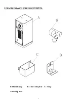
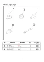
Страница 7: ...6 UNPACKING CHECKING CONTENTS A Main Body B Inlet Adaptor C Tray D Fixing Pad...

Страница 8: ...package NO Description Specification Q TY Part List No A Foot Pad 5 16 4 NO 27 B Nut with cap 5 16 8 NO 28 C Hex Flange Screw 1 4 x1 2 8 NO 10 D Hex Flange Screw 1 4 x3 4 4 NO 18 E Open end Wrench 10x...

Страница 9: ...w NO 10 STEP 1 2 Tight the foot pad NO 27 with the fixing pad NO 29 by using nut with cap NO 28 STEP 1 3 Tight the tray NO 17 on the main body NO 16 with hex flange screw NO 18 See Fig 1 Fig 1 STEP 2...

Страница 10: ...9 PARTS LIST FOR MI 12910...

Страница 11: ...ate 1 MI 12910 20 Phillips Flange Head Screw M4x8 4 MI 12910 21 Strain Relief 8R 1 1 MI 12910 22 Thermal Control Relay 1 MI 12910 23 Phillips Head Screw 3 16 x 1 1 MI 12910 24 Lock Washer External Too...

Отзывы: