Operating Instructions
581E,5811_07
1
Pedestrian Turnstile
Type MPT 33
Страница 1: ...Operating Instructions 581E 5811_07 1 Operating Instructions Pedestrian Turnstile Type MPT 33...
Страница 2: ...allation 11 17 6 Electrical connection 18 19 7 Access control devices 20 8 Commissioning 21 9 Controller MSC 10 22 10 Adjustable parameters 24 11 Operation modes 26 12 Technical support 28 13 Spare pa...
Страница 3: ...out correctly therefore the operating instructions must be read carefully and the safety notes must be observed Any liability and warranty is declined by the manufacturer in the case of incorrect use...
Страница 4: ...ntly hazardous situation which if not avoided will result in death or serious injury The description of the situation is followed by measures of avoidance Please read and observe the given instruction...
Страница 5: ...ng make sure all electrical and functional features are tested The electrical wiring must comply with these instructions Only certified and trained electrical technicians shall perform any electrical...
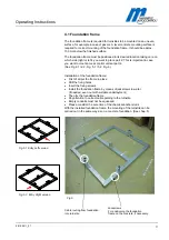
Страница 6: ...ng temperature condition this can cause skin burns 3 Product description The MPT series of turnstiles are designed to control pedestrians entering or exiting restricted areas outside in high security...
Страница 7: ...Operating Instructions 581E 5811_07 7 1 components 3 2 4 Fig 1 Design of components 1 Lock comb 2 Cage half s 3 Upper housing with locking unit 4 Center column...
Страница 8: ...Operating Instructions 581E 5811_07 8 Fig 2 1 Entry left version Fig 2 2 Entry right version Fig 2 Entry left version...
Страница 9: ...d finish a minimum of 5 meters above the finished concrete surface NOTE This foundation is also required in connection with a foundation frame Conduits for mains supply and data lines should finish 50...
Страница 10: ...g empty conduit O 25 mm Foundation smoothed finish to be positioned in water in a level and horizontal manner Lay seperate conduits for power supply and data cables 50 mm approx above foundation All p...
Страница 11: ...e First of all put the frame in place Drill the fixing holes Insert the fixing screws Install the foundation frame by means of jackscrews in water if needed even out with suitable underlayment Then fi...
Страница 12: ...e foundation however do not tighten entirely the bolts in order to compensate any drilling offset which may occur afterwards Use screws 6 x M 10 x35 Grease the screws before Place part 3 upon part 1 a...
Страница 13: ...ion However in this case the turnstile is mounted on the flanges of the foundation frame Fixing of foundation frame see section 4 1 5 3 Opening of the top cover 1 Fig 7 The hood is fixed with 4 hexago...
Страница 14: ...he 8 fixing bolts M8 and plain washer After final positioning tighten all bolts firmly Please consider the home position of the locking unit when mounting the center column Note 1 Mark the dimensions...
Страница 15: ...Operating Instructions 581E 5811_07 15 Fig 9 1 Locking unit Fig 9 2 The home position is reached when the Countersink is in the position as shown fit up aid Fig 9 3 Home Position bottom view...
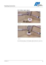
Страница 16: ...Operating Instructions 581E 5811_07 16 5 5 To fit the centre column Mount the lower bearing on the foundation and stick the centre column on it Fig 10 Fig 11...
Страница 17: ...e is in correct position centre in locked position Locking crest in locked position see drawing Fig 12 Center column blocked position Cage halves Cage halves Lock comb Lock comb Center column blocked...
Страница 18: ...HEIT A 1 Fix the center column to the floor bearing using 3 headlees screws 2 Tighten all 3 headless screws equally so that the center column can be rotated smoothly in both directions 3 Secure headle...
Страница 19: ...Operating Instructions 581E 5811_07 19 5 6 Assembly of roof with drain Assemble the roof as shown on Fig 14 The roof can also be mounted rotated by 180 Fig 14...
Страница 20: ...Electrical connections Connection of mains supply should only be performed b y a certified electrian and According to the connecting diagram or after discussion with the supplier Fig 16 Connection un...
Страница 21: ...Operating Instructions 581E 5811_07 21 6 1 Connecting diagram MSC 10 Fig 17...
Страница 22: ...581E 5811_07 22 7 Housings access control units Lead the cable from the rear side of the mounting plate to the steel tube and drill the hole Here for example Fig 18 Mounting plate for access control d...
Страница 23: ...he Turnstile The Turnstile is generally operated by an access control system or control switches Special control panels are also available for operation The center column is rotated manually Center 3...
Страница 24: ...ft normally closed Input 6 proximity switch right normally open Input 7 Resource input For future extensions or special programmes 9 2 Functions of the semiconductor outputs Output 1 Control of soleno...
Страница 25: ...ontroller While the gate is in operation the microcontroller is monitored by watchdog If the device is not triggered regularly by the microcontroller the device will perform a hardware reset watchdog...
Страница 26: ...stored DIP 3 Locking delay time The locking delay time can be activated via DIP 3 in order to avoid that the center column continues its rotation after passage of a person This we recommend in case o...
Страница 27: ...DIP switch 8 is set to ON 11 Operation modes 11 1 Bidirectional pulsed operation without impulse storage If no permanent signal is given to one of the two opening inputs the turnstile operates in pul...
Страница 28: ...s blocked free left respectively blocked free right it is possible to indicate the free direction s If the person begins to pass and the center column is out of its home position the hold open time is...
Страница 29: ...pulsed operation mode In case permanent contact 2 5s is given to an input in pulsed operation mode stored opening pulses will be cleared for the respective direction If the locking delay time is activ...
Страница 30: ...n be retrieved by telephone fax E mail or via the Internet at any time refer to manufacturer s address on Page 2 NOTE In order to enable fast handling note the data of the type plate such as type seri...
Страница 31: ...iehe Ersatzteile 5547 5013 1008 5031 RAL7042 1008 5032 V2A 1008 5033 V4A Siehe Ersatzteile 5547 5032 2059 50 2059 50 2059 50 2059 50 2059 5101 vz 2059 5102 RAL7042 2059 5103 V2A 2059 5104 V4A 2059 517...
Страница 32: ...3307 5000 Fixing nut M12 SS 304 7 3490 5007 Countersunk screw with internal hexagon M12x35 SS 304 8 3307 5000 Fixing nut M12 SS 304 8 3490 5008 Countersunk screw with internal hexagon M12x100 SS 304...
Страница 33: ...t that cam is surely recognized Gap between 0 5 mm and 2 0 mm 01 01 01 01 0 5 2 mm 0 5 2 mm ffner B4 normally closed contact Schlie er B5 normally open contact 15 Warranty conditions Subject to the co...
Страница 34: ...of the device or parts of it at the end of utilisation ensure those noxious and dangerous residues are disposed of in accordance with the regulations Based on the different material disposal must occ...
Страница 35: ...Operating Instructions 581E 5811_07 35 MAGNETIC Autocontrol GmbH Grienmatt 20 D 79650 Schopfheim Germany Tel 49 7622 695 5 Fax 49 7622 695 602 eMail info ac magnetic com www ac magnetic com...