INTRODUCTION
15
Introduction
Drive Description
The DSD 412 Drive is a complete digital
system drive that provides individual drive
and system control in one compact package.
It is of 12SCR Regenerative configuration.
The drive uses two microprocessors, one for
the Power Conversion Unit (PCU) circuitry,
one for the Drive Control Unit (DCU)
circuitry. Interface to other equipment is
provided with Local I/O [Input/Output], or
RS-232 & RS-422 serial communications.
Extensive diagnostics and setup capability
are provided through two Control/Display
Units.
The Standard Control Display Unit
(SCDU)
is mounted on the Drive Control PCB and
consists of a 4-1/2 digit numeric LED
display, four push buttons and
READ/WRITE colored LEDs. The SCDU
can be used for all setup functions and
many diagnostics.
The Portable Control Display Unit
(PCDU)
is an optional hand-held device that can be
plugged into any analog controlled DSD drive and
used for all the same functions as the SCDU plus
some advanced diagnostics. There exists a
version of this PCDU which will work with the
serial version DSD 412, contact Magnetek for
more information. The PCDU has two lines of
sixteen alphanumeric characters and a thirty-key
keypad. Parameters are entered and displayed
in common understandable units. The drive can
be completely setup prior to actual running and
changes can be made during operation. Keypad
entry of changed parameters, protected memory,
and factory default values allow the operator to
modify data with minimum risk to the process.
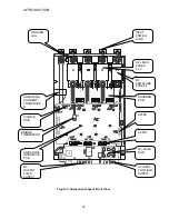
The DSD 412 is a power cube. Depending on
rating of the unit, the power cube is in one of four
chassis sizes. Refer to the outline dimension
drawings furnished in section 6. Each power
cube is designed for mounting inside a qualified
electrical enclosure. Space allowances for air
circulation, additional components, outgoing
terminals, and wire bends must be provided.
Hinged door swing-out clearance is the same as
the width dimension.
Drive Ratings and Specifications
The DSD 412 Elevator Drive is designed to be
connected to a three wire ungrounded power
system, or a four wire grounded or ungrounded
power system.
Basic Drive Specifications
•
10-300 Amps (Special order up to
1285Amps or 600VAC)
•
3 Phase, 48/62 Hz
•
1.0 Service Factor
•
150% full load current for one minute
•
250% full load current for 5 seconds
•
Full-wave six-pulse SCR control
•
Regulation (of set speed) to 0.05% with
digital encoder speed feedback
•
Current regulated shunt field control
•
Automatic Field weakening.
•
Self-adapting to incoming line power
Service Conditions
•
Line voltage 150-525 Vac, ±10%, 3 phase.
•
115 volt, ±10%, 1 phase control power
from a separate source.
•
Frequency 48-62 Hz
•
Operating Temperature 0-45° C (55° C
max at DSD chassis)
•
Altitude to 3300 feet above sea level.
Derate 5% for each 1,000 ft above 3300 ft.
•
Relative Humidity 95% (noncondensing)
Protective Features
•
Programmed memory protection
•
Self-protected Control V power supply
•
Fast phase-back of loop current
•
Contactor interlock for E-Stop
•
I
2
t motor overload protection
•
AC line current limiting fuses
•
Automatic power up test.
•
Control power supply loss detection
•
Isolated and grounded electronics
•
Encoder/Tachometer monitoring and loss
protection.
•
Input line monitoring
•
Phase sequence insensitive
•
dv/dt protection (snubbers)
•
1400 PRV Thyristors
•
Instantaneous over-current protection.
•
Phase loss protection
•
DC bus fuse
•
Field current economizer and loss
protection
Содержание DSD 412
Страница 1: ...DSD 412 DC Elevator Drive Technical Manual CS00407 rev 06...
Страница 6: ...6...
Страница 102: ...MAINTENANCE 102 Figure 24 Connector and E prom Locations...
Страница 103: ...MAINTENANCE 103 Figure 25 Test Point Locations...
Страница 115: ...OUTLINE DRAWING 100A 115 Figure 26 Drive Chassis Outline DSD 412 100 Amp...
Страница 116: ...OUTLINE DRAWING 190A 116 Figure 27 Drive Chassis Outline DSD 412 195 Amp...
Страница 117: ...OUTLINE DRAWING 300A 117 Figure 28 Drive Chasis Outline DSD 412 300 Amp...
Страница 118: ...LAYOUT DRAWING 100A 118 Figure 29 Layout DSD 412 100 Amp A3 A1 A2 A2 L1 NEG GND L2 L3 POS...
Страница 119: ...LAYOUT DRAWING 195A 119 Figure 30 Layout DSD 412 195 Amp A3 A1 A2 A2...
Страница 120: ...LAYOUT DRAWING 300A 120 Figure 31 Layout DSD 412 300 Amp A3 A1 A2 A2...
Страница 121: ......


