background image


(CS)

 3

SR87, CH33

SR87


直线标尺、滑块的安装注意事项

注意

• 

安装直线标尺器之前请勿接通电源。

• 

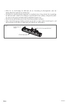
请将直线标尺的开⼝部分朝下安装直线标尺。


如果⽆法使开⼝部分朝下,请使开⼝部分朝向⽔平⽅向。请不要在开⼝部分朝上的状态下安装。


(图

1

• 

请剥掉塞孔周围的涂层,以便通过与直线标尺接触的安装⾯使直线标尺器接地。

• 

请注意,如果移动滑块超出有效长度(

L

)的范围,会损坏直线标尺。

• 

在冷却液可能直接溅到直线标尺的环境下,请⽤外罩将直线标尺盖住,以避免溅上冷却液。


(图

2

1

开⼝部分朝下

开⼝部分朝向⽔平⽅向

开⼝部分朝上

2

冷却液

• 

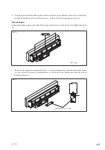
滑块座是在运输时固定滑块⽤的。不能将其作为安装的基准。

• 

到即将固定滑块为⽌,请尽量不要拆卸掉滑块座。

• 

即使拆卸掉滑块座,滑块上装备的塑胶挂钩仍能够维持与直线标尺器的⼤致位置关系。

• 

如果过分⽤⼒扭曲滑块或对其施加外⼒,塑胶挂钩可能会脱落。如果塑胶挂钩脱落,请⾸先将塑胶
挂钩恢复原位,然后进⾏安装操作。

(参见图

4

3

4

运输/固定时的状态

滑块座

L

滑块座

R

塑胶挂钩

塑胶挂钩

滑块座的拆卸⽅法

1. 

解除锁定


将左右滑块座拉杆朝反时针⽅向(插图的位置)旋转。

2. 

拆卸


使滑块座朝外侧滑动,从直线标尺上拆卸滑块座。

步骤

1

步骤

1

步骤

2

步骤

2

拉杆

(

旋转到该位置

)

拉杆

(

旋转到该位置

)

Содержание SR87

Страница 1: ...llation procedures PleaserefertotheInstructionManual soldseparately formoredetailedinformation Lesen Sie die ganze Anleitung vor dem Betrieb aufmerksam durch und folgen Sie beim Betrieb des Ger ts den...

Страница 2: ...S 003 OPERATION IS SUBJECT TO THE FOLLOWING TWO CONDITIONS 1 THIS DEVICE MAY NOT CAUSE HARMFUL INTERFERENCE AND 2 THIS DEVICE MUST ACCEPT ANY INTERFERENCE RECEIVED INCLUDING INTERFERENCE THAT MAY CAUS...

Страница 3: ...J 1 SR87 CH33...

Страница 4: ...2178 1978 1878 1778 1578 1678 1378 1478 1278 1178 1078 978 878 778 478 678 578 278 378 L2 L1 L 3040 2840 2640 2440 2240 2040 1840 1740 1640 1540 1440 1340 1240 1140 1040 940 840 740 640 540 440 340 24...

Страница 5: ...J 3 SR87 CH33 SR87 1 L 2 1 2 4 3 4 L R 1 2 1 1 2 2...

Страница 6: ...4 J SR87 CH33 5 5 M4 20 2 7 N m M6 9 N m M6 35 9 N m...

Страница 7: ...J 5 SR87 CH33 1 1 6 mm 50 0 05 MG 0 05 MG 0 05 0 05 2 7 mm 78 0 3 5 0 2 0 05 MG 78 0 3 78 0 3 0 05...

Страница 8: ...6 J SR87 CH33 3 8 2 1 9 mm 78 0 3 5 0 2 78 0 3 0 05 MG 0 05 MG 0 05...

Страница 9: ...J 7 SR87 CH33 2 10 0 1 MG mm 3 t 1 0 mm 11 t 1 0 mm...

Страница 10: ...8 J SR87 CH33 3 1 M4 2 M4 M4 3 M6 M4 M4 8 M4 2 7 N m M4 M4 7 M4 2 7 N m M6 9 N m M6 M6 M5...

Страница 11: ...J 9 SR87 CH33 CH33 CH33 SR87 0 36 N m 4 1 2 2 0 V 0 V 0 V 0 V 5 V 5 V 5 V 5 V CNT 3 CNT 3 N C 4 N C 4 SD N C 4 SD N C 4 RQ SD RQ RQ SD RQ 1 4 2 2 3 CNT 4 N C 5 V 0 V 2 2 1...

Страница 12: ...10 J SR87 CH33...

Страница 13: ...ation work with wet hands as this may result in electric shock Do not disassemble or modify the unit as this may result in injury or damage the internal circuits Caution Be sure to check the machine a...

Страница 14: ...10 9 8 7 6 5 4 3 n 2300 2100 1900 1800 1700 1600 1500 1400 1300 1200 1100 1000 900 800 600 700 500 400 300 200 3100 2900 2700 2500 3178 2978 2778 2578 2378 2178 1978 1878 1778 1578 1678 1378 1478 1278...

Страница 15: ...cure the slider in place during transport They are not guides for installation Do not take off the slider holders if possible until immediately before securing the slider Even if the slider holders ar...

Страница 16: ...the entire scale length Even when using divided brackets be sure to always check that the alignment of the installation brackets is within the standards The rear surface of the scale unit is used as t...

Страница 17: ...the scale bracket s parallelism with respect to the machine guide and then secure in place Even when using divided brackets adjust the parallelism over the entire bracket length as shown in the figure...

Страница 18: ...with the bracket 1 Adjust the parallelism of the scale bracket and slider bracket with respect to the machine guide and then secure in place Adjust the height and parallelism of the slider bracket wi...

Страница 19: ...l gauge Tighten the set screws Measurement method Measure near the installation hole positions at the scale unit rear Fig 10 0 1 MG Unit mm 3 Insert the supplied spacer t 1 0 mm in the space between t...

Страница 20: ...he nut position is limited by the rubber bushing pay careful attention to the tolerance of the slider mounting holes Pattern 3 The M6 hex socket head cap screws must be supplied by the customer M4 M4...

Страница 21: ...5 V Violet 5 V 5 V Blue CNT Note 1 CNT Note 1 Yellow N C Note 2 N C Note 2 Orange SD N C Note 2 Gray SD N C Note 2 Red RQ SD RQ White RQ SD RQ Note 1 The CNT terminal is for service maintenance Do not...

Страница 22: ...10 E SR87 CH33...

Страница 23: ...besteht F hren Sie Installationsarbeiten nicht mit nassen H nden aus da hierbei die Gefahr elektrischer Schl ge besonders gro ist Unterlassen Sie jeden Versuch das Ger t zu zerlegen oder umzubauen da...

Страница 24: ...12 11 10 9 8 7 6 5 4 3 n 2300 2100 1900 1800 1700 1600 1500 1400 1300 1200 1100 1000 900 800 600 700 500 400 300 200 3100 2900 2700 2500 3178 2978 2778 2578 2378 2178 1978 1878 1778 1578 1678 1378 14...

Страница 25: ...K hlmittel Die Schieberhalter dienen zur Sicherung des Schiebers w hrend des Transports Sie sind keine F hrungen f r die Installation Nehmen Sie die Schieberhalter nach M glichkeit erst unmittelbar v...

Страница 26: ...Verwendung von geteilten Haltern muss immer sichergestellt werden dass die Ausrichtung der Installationshalter innerhalb der Normen liegt Die R ckseite der Ma stabseinheit wird als Installationsricht...

Страница 27: ...Bezug auf die Maschinenf hrung berpr fen und einstellen und dann das Teil befestigen Selbst wenn geteilte Halter verwendet werden muss die Parallelit t ber die gesamte Halterl nge eingestellt werden...

Страница 28: ...ter erzeugt wird 1 Die Parallelit t von Ma stabshalter und Schieberhalter in Bezug auf die Maschinenf hrung einstellen und dann die Teile befestigen H he und Parallelit t des Schieberhalters in Bezug...

Страница 29: ...chrauben an Messmethode Nehmen Sie die Messungen in der N he der Montagelochpositionen auf der R ckseite der Ma stabseinheit vor Abb 10 0 1 MG Einheit mm 3 F hren Sie das mitgelieferte Abstandsst ck t...

Страница 30: ...Mutternposition durch die Gummibuchse begrenzt wird istdieToleranzderSchieber Montagel chersorgf ltig zu beachten Muster 3 Die M6 Innensechskantschrauben sind vom Kunden bereitzustellen M4 M4 Mutter...

Страница 31: ...e die Verbindung nicht her Hinweis 2 N C Signal nicht angelegt Hinweise Da immer jeweils zwei Kabel f r 5 V und 0 V vorhanden sind m ssen diese Kabel paarweise angeschlossen werden wenn keine Stromver...

Страница 32: ...10 G SR87 CH33...

Страница 33: ...CS 1 SR87 CH33 Magnescale Co Ltd...

Страница 34: ...2178 1978 1878 1778 1578 1678 1378 1478 1278 1178 1078 978 878 778 478 678 578 278 378 L2 L1 L 3040 2840 2640 2440 2240 2040 1840 1740 1640 1540 1440 1340 1240 1140 1040 940 840 740 640 540 440 340 2...

Страница 35: ...CS 3 SR87 CH33 SR87 1 L 2 1 2 4 3 4 L R 1 2 1 1 2 2...

Страница 36: ...4 CS SR87 CH33 5 5 M4 20 2 7 N m M6 9 N m M6 35 9 N m...

Страница 37: ...CS 5 SR87 CH33 1 1 6 mm 50 0 05 MG 0 05 MG 0 05 0 05 2 7 mm 78 0 3 5 0 2 0 05 MG 78 0 3 78 0 3 0 05...

Страница 38: ...6 CS SR87 CH33 3 8 2 1 9 mm 78 0 3 5 0 2 78 0 3 0 05 MG 0 05 MG 0 05...

Страница 39: ...CS 7 SR87 CH33 2 10 0 1 MG mm 3 t 1 0 mm 11 t 1 0 mm...

Страница 40: ...8 CS SR87 CH33 3 1 M4 2 M4 M4 3 M6 M4 M4 8 mm M4 2 7 N m M4 M4 7 mm M4 2 7 N m M6 9 N m M6 M6 M5...

Страница 41: ...CS 9 SR87 CH33 CH33 CH33 SR87 0 36 N m 4 1 2 2 0 V 0 V 0 V 0 V 5 V 5 V 5 V 5 V CNT 3 CNT 3 N C 4 N C 4 SD N C 4 SD N C 4 RQ SD RQ RQ SD RQ 1 4 2 2 3 CNT 4 5 V 0 V 5 V 0 V...

Страница 42: ...ent l usage des acqu reurs de l quipement d crit dans ce manuel Magnescale Co Ltd interdit formellement la copie de quelque partie que ce soit de ce manuel ou son emploi pour tout autre but que des op...

Страница 43: ...SR87 CH33 1...

Страница 44: ...5 Suzukawa Isehara shi Kanagawa 259 1146 Japan For foreign customers Note This product or technology may be restricted by the government in your country Please make sure that end use end user and coun...

Отзывы: