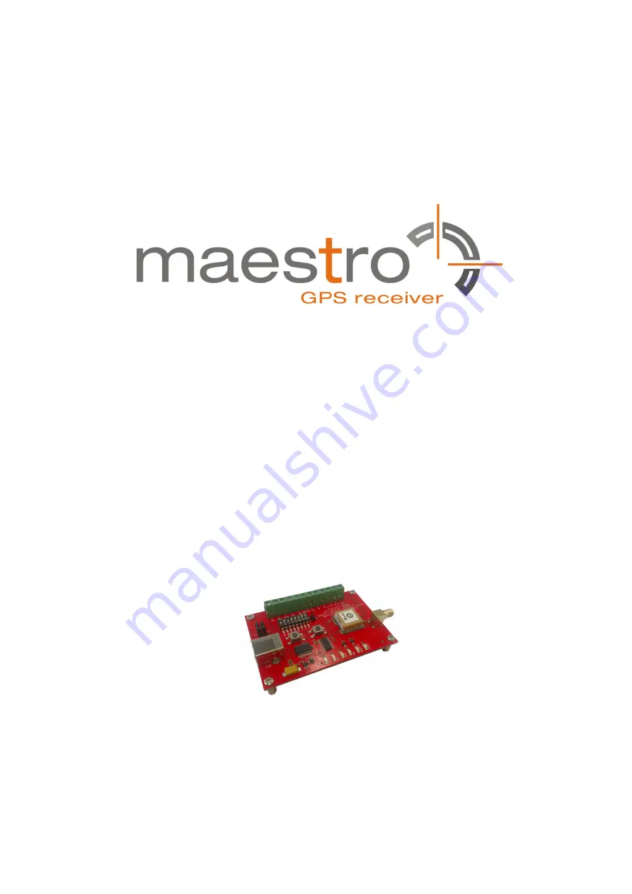
GPS Evaluation Kit EVA2135-H
A Description of the Evaluation Board
for Maestro’s GPS Receiver / Smart Antenna Module A2135-H
User’s Manual
Version 0.1
Страница 1: ...GPS Evaluation Kit EVA2135 H A Description of the Evaluation Board for Maestro s GPS Receiver Smart Antenna Module A2135 H User s Manual Version 0 1 ...
Страница 2: ...e 2 of 17 Revision History Rev Date Description 0 1 06 23 14 Initial Draft mm dd yy Name Date Signature Written by Happy wen 06 23 14 H W Checked by Sam Law Matthieu 06 23 14 S L M Approval by Frank Tang Calvin Yau 06 23 14 F T C Y ...
Страница 3: ...D FOR USE IN LIFE SUPPORT DEVICES OR SYSTEMS WITHOUT THE EXPRESS WRITTEN APPROVAL OF MAESTRO THIS DOCUMENT MAY PROVIDE LINKS TO OTHER WORLD WIDE WEB SITES OR RESOURCES BECAUSE MAESTRO HAS NO CONTROL OVER SUCH SITES AND RESOURCES MAESTRO SHALL NOT BE RESPONSIBLE FOR THE AVAILABILITY OF SUCH EXTERNAL SITES OR RESOURCES AND DOES NOT ENDORSE AND IS NOT RESPONSIBLE OR LIABLE FOR ANY CONTENT ADVERTISING...
Страница 4: ...rd Peripherals 9 4 1 RESET and ON_OFF Push Button 9 4 2 External Antenna Connector 9 5 LED s 10 6 Design in Support 11 6 1 Terminal Block 11 6 2 DIP Switch Settings 12 6 3 ICC Jumper 13 7 NMEA Port 13 8 Board Overview 14 9 Board Schematics 15 10 Related Information 16 10 1 Contact 16 10 2 Related Documents 16 10 3 Related Tools 16 11 List of Figures 17 12 List of Tables 17 ...
Страница 5: ... in The signals provided on the Evaluation Kit allow direct integration into a sur rounding system making it an ideal development tool The EVA2135 H can especially demonstrate that the on module GPS antenna and an external active GPS antenna connected to the External Antenna input will result in outstanding GPS performance The user can switch between the two antennas with the ANT_SW signal provide...
Страница 6: ...ws logo testing with a warning Figure 1 Windows driver installation warning Note After successful driver installation Windows might interpret the data coming over the serial interface as a serial ballpoint mouse Your mouse pointer can start jumping around To stop this disable the according device using your device manager Leave the EVA2135 H kit connected and press and keep pressing the reset butt...
Страница 7: ...this by selecting COM port connection A detailed description of the GPS Cockpit software is included on the CD ROM In any case the following window will appear Figure 3 GPS Cockpit communication window blank Activate Terminal 1 choose the COM port to which the GPS receiver is con nected verify in your system settings device manager which communication port is used for this USB serial connection in...
Страница 8: ...ual Page 8 of 17 Figure 5 GPS Cockpit NMEA terminal with NMEA data Now you can start using all the other windows and features of GPS Cockpit Please refer also to the GPS Cockpit manual and the online help within GPS Cockpit ...
Страница 9: ...s button the module starts again from the beginning 4 2 External Antenna Connector The A2135 H supports two antenna inputs The on module antenna The antenna connector External Antenna leads to pin 10 of the A2135 H GPS receiver which supports active GPS antennas It can be switched between the two antenna inputs by using the ANT_SW pin of the A2135 H connected to the DIP switch on board the EVA2135...
Страница 10: ...raffic from GPS receiver D1 RX Receive Serial data traffic into GPS receiver D5 1PPS Timing 1PPS signal at rising edge 1 pulse per second duration 500ms typ D3 ON_OFF Hibernate Toggle hibernate mode position request during PTF cycle the LED visualizes the ON_OFF pulse D4 WAKEUP Operational state HIGH Full operation LOW Module in a low power mode D6 Power VCC POWER Power on LED Table 1 LED s functi...
Страница 11: ...d against reversed polarity External supply has to be within the range of 3 3 to 3 6 VDC 6 1 Terminal Block The terminal block offers direct access to the A2135 H GPS receiver pins Pin Port 1 VCC 2 GPIO7 SPI chip select pin when module works in SPI mode 3 GPIO6 SPI clock pin when module works in SPI mode 4 nRST 5 ON_OFF 6 Host Port I2C_CLK 7 GND 8 TX SPI data out pin when module works in SPI mode ...
Страница 12: ...IP switches Switch Function Operation via USB connector default settings Operation via terminal block S1 GPIO7 OFF OFF S2 GPIO6 ON OFF S3 ANT_SW ON high A2135 H pin 10 external ac tive antenna not applicable OFF low A2135 H on module antenna S4 nRST ON OFF S5 ON_OFF ON OFF S6 TX ON OFF S7 RX ON OFF S8 VCC ON OFF Table 3 Switch settings ...
Страница 13: ... the current draw of the A2135 H GPS receiver can be measured directly by connecting a low resistance measurement device to the ICC jumper The low resistance measurement device should be connected before VCC is switched off 7 NMEA Port Default setting 4800 baud 8 data bits no parity 1 stop bit no flow control Standard NMEA 0183 output on NMEA baud rate selectable Standard USB connectors ...
Страница 14: ...V0 1 Oct 14 User s Manual Page 14 of 17 8 Board Overview Figure 11 Board overview ...
Страница 15: ...V0 1 Oct 14 User s Manual Page 15 of 17 9 Board Schematics Figure 12 EVA2135 H board schematics ...
Страница 16: ...ons and comments or proposals to Maestro Hong Kong for further improvements are highly appreciated Maestro Wireless Solutions Limited Units A B 9th Floor Wing Cheong Factory Building 121 King Lam Street Cheung Sha Wan Kowloon Hong Kong Tel 852 3955 0222 Fax 852 3568 4833 support gps maestro wireless com www maestro wireless com 10 2 Related Documents GPS Receiver A2135 H Maestro 10 3 Related Tools...
Страница 17: ...munication window COM2 7 Figure 5 GPS Cockpit NMEA terminal with NMEA data 8 Figure 6 On module antenna and External Antenna Connector 9 Figure 7 EVA2135 H LED s 10 Figure 8 Terminal block 11 Figure 9 DIP switches 12 Figure 10 ICC jumper 13 Figure 11 Board overview 14 Figure 12 EVA2135 H board schematics 15 12 List of Tables Table 1 LED s function and description 10 Table 2 Terminal block descript...