OWNER'S MANUAL
BEDIENUNGSANLEITUNG
MANUEL D'EMPLOI
MANUALE D'ISTRUZIONI
MANUAL DE INSTRUCCIONES
CAR AUDIO EQUIPMENT
®
42.1542.17
POWER AMPLIFIER, BRIDGEABLE FORSIMULTANEOUS STEREO/MONOOUTPUT,MOS-FET POWER SUPPLY,DISCRETE COMPONENTS FINAL STAGE
Страница 1: ...NGSANLEITUNG MANUEL D EMPLOI MANUALE D ISTRUZIONI MANUAL DE INSTRUCCIONES CAR AUDIO EQUIPMENT 42 15 42 17 POWER AMPLIFIER BRIDGEABLE FOR SIMULTANEOUS STEREO MONO OUTPUT MOS FET POWER SUPPLY DISCRETE C...
Страница 2: ...LATION AND SWITCH 11 TECHNICAL DATA 12 DEUTSCH EINFUHRUNG 13 VORSICHT 13 MERKMALE 14 15 STEUERUNGEN UND ANZEIGEN 15 EINBAU 15 ANSCHLUSSE 16 EINSTELLUNGEN UND SCHALTUNG 17 TECHNISCHE ANGABEN 18 FRANCAI...
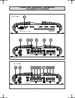
Страница 3: ...GND REMOTE 0 5V 0 1V 2V L R 15 A BR IDG ED GAIN CONTR OL 7 6 5 4 3 2 CONNECTIONS ANSCHLUSSE CONNEXIONES COLLEGAMENTI CONEXIONES 1 4 Fig 2 abb 2 Fig 3 abb 3 POWER ON R L m ono BATT GND REMOTE 0 5V 0 1...
Страница 4: ...ATION Left channel Right channel 1 CHANNEL CONFIGURATION Left channel Left Right Mono Left Right Mono SYSTEM DIAGRAM SYSTEM DIAGRAMM EXEMPLES DE SYSTEME DIAGRAMMA DI SISTEMA DIAGRAMA DEL SISTEMA Note...
Страница 5: ...GRAMMA DI SISTEMA DIAGRAMA DEL SISTEMA 59 16 59 10 57 00 59 16 59 10 57 00 95 83 95 83 59 25 59 25 Audio Signal MONO Audio Signal Two channel configuration 59 16 59 10 57 00 59 16 59 10 57 00 95 83 95...
Страница 6: ...ir the unit yourself If repairs are ever needed take the unit to your MACROM dealer or to your nearest MACROM service station 6 In order to obtain the best possible performance from this unit make sur...
Страница 7: ...Vsensitivity for ideal coupling with MACROM sources and however it is possible to regulate the sensitivity from 100mV to 2V to facilitate coupling with any other source present on the market REMOTE ON...
Страница 8: ...ignal selector Input gain control Speaker output connector board Fuse Power supply connector board INSTALLATION INSTALLATION Fig 1 page 3 Due to the high output power of the amplifier a great amount o...
Страница 9: ...ead unit to the REMOTE terminal NOTE If this lead is not connected the amplifier will not be switched on when the head unit is switched on If your head unit is not fitted with an outlet for a power an...
Страница 10: ...cted corresponding to the preamplified outputs of MACROM products If the amplifier is to be connected to a head unit that is not of MACROM make but is fitted with preamplified RCA outputs proceed as f...
Страница 11: ...Maximum power 4 Ohm 1 kHz 200W Frequency response 0 1dB 10 50 000 Hz S N signal to noise ratio INFA weighted 105 dB Input sensitivity Impedance for nominal power output Control in mid position 500 mV...
Страница 12: ...e auf keinen Fall das Ger t selbst zu reparieren Wenden Sie sich an Ihren MACROM H ndler oder an eine MACROM Dienststelle 6 Vor dem Einschalten des Ger tes sicherstellen da die Temperatur im Fahrzeugr...
Страница 13: ...schluss eines MACROM Ger tes Es besteht die M glichkeit die Empfindlichkeit von 100mV auf 2V zu regulieren um den Anschluss von anderen Fabrikaten zu erleichtern EIN UND AUSSCHALTEN AUF DISTANZ Der Ve...
Страница 14: ...u des Stereo oder Mono Eingangssignals W hlschalter f r Stereo oder Mono Eingangssignal Eingangsgewinnsteuerung Anschlu brett Lautsprecherausg nge Sicherung Versorgungs Anschlu klemmen INSTALLATION Ab...
Страница 15: ...t nicht ber einen Ausgang f r eine elektrische Antenne so mu ein schnellausl sender Hebelschalter SPST zwischen die Stromquelle 12 V und das REMOTE Einschaltkabel geschaltet und an die REMOTE Klemme...
Страница 16: ...Tieft nersystems verwendetwird dasdenrechtenundlinkenKanalinAnspruch nimmt Die beiden Eing nge werden so gemischt dass man ein einziges Mono Ausgangssignal erh lt verteilt auf die beiden Kan le oder a...
Страница 17: ...g bei GEBRIDGTEM Verst rker Maximale Leistung bei 4 Ohm 1 kHz 200W Frequenzgang 0 1 dB 10 50 000 Hz Ger uschabstand INFA gew gt 105 dB Eingangsempfindlichkeit Impedanz f r Ausgangs Nennleistung Steuer...
Страница 18: ...le fil de la batterie au terminal de la batterie m me en dernier et seulement apr s avoir termin et contr l toutes les autres connexions 3 A cause de la puissance du 42 15 42 17 il est indispensable q...
Страница 19: ...pour l id ale connexion avec des sources MACROM En tout cas il est possible de r gler la sensibilit entre 100mV et 2V pour une connexion facile avec les autres sources pr sentes sur le march ALLUMAGE...
Страница 20: ...r du signal d entr e st r o ou mono Contr le du gain l entr e Plaque bornes sorties haut parleurs Fusible Plaque bornes de l alimentation INSTALLATION INSTALLATION Fig 1 page 3 A cause de la sortie en...
Страница 21: ...r l antenne lectrique il faut relier un interrupteur levier d clenchement rapide SPST entre la source d allumage 12 V et le fil d allumage distance qui doit tre reli la borne REMOTE pour effectuer l a...
Страница 22: ...plificateurestutilis pourunsyst medesubwoofer utilisant les canaux droit et gauche Les deux entr es seront ainsim lang esetl onobtientunseulsignalmonophoniquede sortie distribu sur deux canaux ou sur...
Страница 23: ...4 Ohm 1 kHz 200W R ponse en fr quence 0 1dB 10 50 000 Hz Rapport signal bruit pes INFA 105 dB Sensibilit d entr e imp dance pour la sortie en puissance nominale Contr le avec position centrale 500 mV...
Страница 24: ...re per ultimo il filo della batteria al terminale della stessa e solo dopo aver completato e controllato tutti gli altri collegamenti 3 A causa della potenza del 42 15 42 17 indispensabile che tutti i...
Страница 25: ...lit a 500 mV per l ideale accoppiamento con sorgenti MACROM comunque possibile regolare la sensibilit da 100mV a 2V per un facile accoppiamento con qualunque sorgente presente nel mercato ACCENSIONE E...
Страница 26: ...a con nella figura per assicurare un buon contatto di massa INSTALLAZIONE ALIMENTAZIONE A MOS FET L alta potenza del 42 15 42 17 ottenuta tramite l impiego di un sofisticato alimentatore a C MOS FET p...
Страница 27: ...ore non si accender all accensione dell unit principale Nel caso in cui la vostra unit principale non disponesse di un uscita per l antenna elettrica di potenza bisogna collegare un interruttore a lev...
Страница 28: ...ali destro e sinistro I due ingressi verrannocos miscelatiottenendoununicosegnalemonofonico in uscita ripartito su i due canali o su un canale al doppio dela potenza se il Sub Woofer collegato al cana...
Страница 29: ...a in frequenza 0 1dB 10 50 000Hz Rapporto segnale rumore pesato INFA 105 dB Sensibilit d ingresso impedenza per l uscita di potenza nominale Controllo con posizione centrale 500mV 10k Ohm Controllo Va...
Страница 30: ...indicadas en este manual 2 Con cten por ltimo el cable de la bater a al terminal de la misma y unicamente tras haber completado y controlado las dem s conexiones 3 Debido a la potencia del 42 15 42 1...
Страница 31: ...00 mV para el acoplamiento ideal con fuentes MACROM De todos modos se puede ajustar la sensibilidad de manera continua de 100 mV a 2 V para acoplarlo facilmente con otras fuentes presentes en el merca...
Страница 32: ...l Est reo o Mono en entrada Control de ganancia en entrada Cuadro de bornes salida altavoces Fusibles Cuadro de bornes de alimentaci n INSTALACION INSTALACION Fig 1 pag 3 Debido a la salida de alta po...
Страница 33: ...n caso de no conexi n de este cable el amplificador no se encender al encender la unidad principal Si la unidad principal de Uds no tuviera salida para la antena el ctrica de potencia habr queconectar...
Страница 34: ...les derecho y izquierdo Las dos entradas se mezclar n as obteniendo una sola se al monof nica en salida repartida por los dos canales o por un solo canal con el doble de la potencia si el subwoofer es...
Страница 35: ...200Wx2 Respuesta en frecuencia 0 1 dB 10 50 000 Hz Relaci n se al ruido pesado INFA 105 dB Sensibilidad de entrada impedancia para salida de potencia nominal Control con posici n central 500 mV 10 kO...
Страница 36: ...DEL SISTEMA 59 16 59 10 57 00 59 16 57 04 59 16 57 04 95 82s 59 10 57 00 59 16 95 82s 95 83 95 83 59 25 Audio Signal MONO 59 25 Power Amplifier 42 17 Power Amplifier 42 15 Power Amplifier 42 15 MONO...
Страница 37: ...STEM DIAGRAMM EXEMPLES DE SYSTEME DIAGRAMMA DI SISTEMA DIAGRAMA DEL SISTEMA Power Amplifier 42 17 Audio Signal Electronic Crossover 48 13 Power Amplifier 42 15 Power Amplifier 42 15 59 16 59 10 57 00...