background image

OM-154 500 Page 2

SECTION 2 – INSTALLATION

2-1.

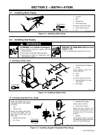
Installing Work Clamp

1

Insulator

2

Bolt

3

Smaller Hole

4

Work Clamp Tabs

Bend tabs around work cable.

5

Work Cable From Unit

6

Nut

Ref. ST-025 190-C

Tools Needed:

3/8, 7/16 in

1

2

3

4

5

6

Figure 2-1. Installing Work Clamp

2-2.

Installing Gas Supply

WARNING

CYLINDERS can explode if damaged.

Keep cylinders away from welding and other
electrical circuits.

Never touch cylinder with welding electrode.

Always secure cylinder to running gear, wall, or
other stationary support.

BUILDUP OF SHIELDING GAS can harm
health or kill.

Shut off shielding gas supply when not in use.

warn4.1 9/91

 A . Installing Safety Chain

1

Cylinder Bracket As Shipped

2

S-Hook

Crimp between small hole in
bracket and chain.

3

Chain

4

Snap

Crimp onto open end of chain.

5

Cylinder Bracket For Large
Gas Cylinder

6

Gas Fitting

ST-160 791

1

2

3

Tools Needed:

4

5

6

Figure 2-2. Installing Safety Chain

 B . Installing  Regulator/Flow  Gauge

Obtain gas cylinder and chain to
running gear, wall, or other station-
ary support.

1

Cap

2

Cylinder Valve

Remove cap, stand to side of valve,
and open valve slightly. Gas flow
blows dust and dirt from valve.
Close valve.

3

Cylinder (CO

2

 shown)

4

CO

2

 O-Ring

ssb3.1* 12/92 – ST-154 583 / ST-154 623 / Ref. ST- 800 746

Tools Needed:

1-1/8, 5/8 in

5

6

2

3

4

1

5

Regulator/Flow Gauge

Install so face is vertical.

6

Gas Hose Connection

Install gas hose between flow
Gauge and welding power source.

Flow rate is set to 20 cfh (cubic feet
per hour).

7

Adapter

Install adapter between regulator/
flow gauge and cylinder when using
argon or mixed shielding gas.

7

Figure 2-3. Installing Supplied Regulator/Flow Gauge

Содержание MW150K

Страница 1: ...carefully Have only trained and qualified persons install operate or service this unit Call your distributor if you do not understand the directions Give this manual to the operator For help call you...

Страница 2: ...undersized or poorly spliced cables 8 Do not wrap cables around your body 9 Ground the workpiece to a good electrical earth ground 10 Do not touch electrode while in contact with the work ground circu...

Страница 3: ...de to touch any cylinder 5 Use only correct shielding gas cylinders regulators hoses and fittings designed for the specific application maintain them and associated parts in good condition 6 Turn face...

Страница 4: ...Gun Rated Output Air Cooled 160 Amperes At 60 Duty Cycle Using CO2 Shielding Gas Cable Length 10 ft 3 m 1 1 Volt Ampere Curve And Duty Cycle Chart CAUTION USING GUN BEYOND DUTY CYCLE RATING can damage...

Страница 5: ...e in bracket and chain 3 Chain 4 Snap Crimp onto open end of chain 5 Cylinder Bracket For Large Gas Cylinder 6 Gas Fitting ST 160 791 1 2 3 Tools Needed 4 5 6 Figure 2 2 Installing Safety Chain B Inst...

Страница 6: ...door Ref ST 149 629 B 2 4 1 3 Figure 2 5 Gun Connections 2 5 Connecting Input Power Table 2 1 Electrical Service Requirements Input Voltage 230 Input Amperes At Rated Output 20 Recommended Standard F...

Страница 7: ...tacle 4 Input Conductors 5 Grounding Conductor Select size and length using Table 2 1 Conductor rating must comply with national state and lo cal electrical codes Install and connect input conduc tors...

Страница 8: ...e Spool 2 Hub Tension Nut Grasp spool in one hand and turn while using a wrench to adjust nut When a slight force is needed to turn spool tension is set Loosen wire from spool and cut off bent wire an...

Страница 9: ...oltage Adjustment switch position while welding Arcing inside switch can damage contacts causing switch to fail READ SAFETY BLOCKS at beginning of manual before proceeding WARNING 1 1 Insulating Glove...

Страница 10: ...oltage Adjustment Switch Use switch to select an arc voltage The higher the selected number the thicker the material that can be welded see Table 3 1 3 Power Switch Use switch to turn unit On and Off...

Страница 11: ...80 3 60 3 50 3 90 3 70 3 60 2 45 2 40 3 90 3 65 3 50 3 80 3 85 2 2 1 1 1 70 60 55 45 35 2 2 1 1 60 50 40 30 2 1 1 1 40 30 20 15 2 2 1 1 1 80 70 60 50 40 2 2 1 1 60 50 30 45 2 2 1 3 50 40 33 25 1 1 1...

Страница 12: ...r Clean and check wire drive parts replace as necessary Every 3 months Tape or replace cracked cables clean and tighten connections Replace unreadable labels Every 6 months Blow out or vacuum inside o...

Страница 13: ...ARNING Turn Off and unplug unit 1 Wire Spool 2 Gun Contact Tube Cut welding wire off at contact tube Retract wire onto spool and secure 3 Pressure Roll Arm 4 Cotter Pin 5 Pin 6 Screw 7 Bearing Remove...

Страница 14: ...ut liner off Reinstall gun so that liner is as close as possible to drive rolls without touch ing Thread welding wire see Section 2 6 Close door Ref ST 149 629 C Ref ST 155 509 Tools Needed 3 8 in 3 2...

Страница 15: ...nlet guide or liner if dirty or plugged 4 3 4 4 Replace drive roll or pressure bearing if worn or slipping 4 3 Secure gun trigger plug in receptacle or repair leads or replace trig ger switch 2 4 Chec...

Страница 16: ...OM 154 500 Page 13 Figure 5 2 Wiring Diagram For Welding Power Source SC 163 085...

Страница 17: ...RTS LIST ST 155 497 B Figure 6 1 Main Assembly 1 2 3 4 5 6 7 18 9 10 11 12 13 14 20 21 22 23 24 8 15 16 17 25 26 27 28 29 30 31 32 33 34 35 36 37 38 39 40 41 42 43 44 45 46 47 48 26 27 49 50 51 52 53...

Страница 18: ...572 Bracket 52 Rear Panel w Cmpts 128 751 Gas Valve 605 227 Nyl Nut gas valve 152 118 Cord Set 111 443 Bushing cord set 147 443 Rear Panel 146 619 Bezel 147 548 Speed Nut 156 339 Bottle Retainer 602 3...

Страница 19: ...Notes...

Страница 20: ......

Отзывы: