OM-154 500 Page 10
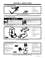
B. Motor Fuse F1
CAUTION
STATIC ELECTRICITY can damage parts on circuit boards.
•
Put on grounded wrist strap BEFORE handling boards or parts.
fwarn5.1* 9/91
Turn Off and unplug unit. Unlatch
door, and remove door/wrapper.
1
Motor Control Board PC1
2
Fuse F1 (See Parts List For
Rating)
If F1 opens, wire does not feed.
Pull fuse from fuse holder on PC1.
To reinstall, push fuse into fuse
holder.
Reinstall wrapper, and latch door.
Ref. ST-150 194-B / ST-149 921-A
1
2
Figure 4-1. Fuse F1 Location
4-3.
Drive Assembly Maintenance
READ SAFETY BLOCKS at start of
Section 4 before proceeding.
WARNING
Turn Off and unplug unit.
1
Wire Spool
2
Gun Contact Tube
Cut welding wire off at contact tube.
Retract wire onto spool and secure.
3
Pressure Roll Arm
4
Cotter Pin
5
Pin
6
Screw
7
Bearing
Remove bearing as shown. Install
new bearing and secure with screw.
Reinstall arm onto pin and secure
with cotter pin.
8
Screw
9
Drive Roll
Remove drive roll as shown.
Use a wire brush to clean drive roll.
Push drive roll onto shaft and rein-
stall screw and washers.
10 Wire Inlet Guide
Remove guide by pressing on
barbed area or cutting off one end
near housing and pulling it out of
hole. Push new guide into hole from
rear until it snaps in place.
Thread welding wire (see Section
2-6). Close door.
Ref. ST-150 193-C / ST-155 578
3
4
5
6
7
9
8
10
10
1
Tools Needed:
2
Figure 4-2. Drive Assembly Maintenance
Содержание MW150K
Страница 16: ...OM 154 500 Page 13 Figure 5 2 Wiring Diagram For Welding Power Source SC 163 085...
Страница 19: ...Notes...
Страница 20: ......


