M2 Antenna Systems, Inc. 4402 N. Selland Ave. Fresno, CA 93722
Tel: (559) 432-8873 Fax: (559) 432-3059 Web: www.m2inc.com
©2014 M2 Antenna Systems Incorporated
07/31/09
Rev.01
Model ........................................ 10M4DX
Frequency Range ...................... 28.0 To 28.8 MHz
*
Gain, (FS) / Over gnd ............... 10.1dBi / 15.7dBi @35’
Front to back .............................. 22 dB Typical
Beamwidth ............................... E=53° / H=68°
Feed type ................................... Hair pin match
Feed Impedance........................ 50 Ohms Unbalanced
Maximum VSWR ....................... 1.2:1
Input Connector ......................... SO-239, Others avl.
Power Handling ......................... 3 kW, Higher avl.
Boom Length / Dia ..................... 24’ / 2” x .065 Wall
Element Length / Dia. ................ 18.5’ / 1” To 1/2”
Turning Radius: ......................... 14’ 8”
Stacking Distance ...................... 25’ To 31’
Mast Size ................................... 2” to 3 ” Nom.
Wind area / Survival .................. 3.5 Sq. Ft. / 100 MPH
Weight / Ship Wt. ....................... 38 Lbs. / 41 Lbs.
M2 Antenna Systems, Inc.
Model No: 10M4DX
FEATURES:
The 10M4DX was designed for high performance while keeping weight, wind area and costs low. Using computer
optimization techniques, we have squeezed for excellent performance on both the CW and phone. The 10M4DX is a
great antenna to stack with more 10M4DX Yagis or with other HF antennas. Mechanically, CNC machined aluminum
(6061-T6) ring clamps ground the elements to the boom and make assembly a snap. A hairpin type match couples the 3
kW 1: balun to the feed line. The antenna is completely DC grounded. Great effort has been put into making sure this an-
tenna stays in the air for years to come while providing enjoyment and satisfaction along the way.
SPECIFICATIONS:
*Subtract 2.14 from dBi for dBd / FS = Free Space
Содержание 10M4DX
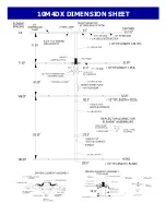
Страница 4: ...10M4DX DIMENSION SHEET...
Страница 5: ...D E PARASITIC ELEMENT DETAIL...
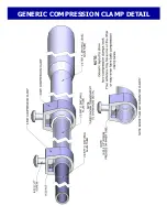
Страница 6: ...GENERIC COMPRESSION CLAMP DETAIL...


