


Page 28 of 51
(North America Edition)
©2019 Lytx, Inc. - Confidential & Proprietary.
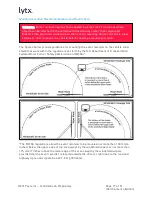
4. Insert the vehicle’s J1939 wires into the CAN Coupler with the yellow wire on the CAN-
HI (Y) side and the green wire on the CAN-LO (G) side. Ensure that the wires are
secured in the tabs provided and properly oriented.
5. Place the cap on the CAN Coupler.
Connect Turn Signals and Brake Inputs (ER-SF300 devices only)
Before You Begin
l
Refer to the manufacturer-specific connection guide for possible locations to find
turn signal and brake inputs.
l
Check with the vehicle manufacturer to determine if brake data is reported on the
J1939 vehicle network. Brake data is reported on most vehicles with J1939
vehicle networks manufactured since 2008.
To install ER-SF300 devices:
1. Connect one of the remaining input wires on the Vehicle Interface Cable to the left turn
signal input. Typically, the white wire is used.
2. Connect one of the remaining input wires on the cable to the right turn signal input.
Typically, the purple wire is used.
3. Cap off and coil the remaining unused wire. If the white and purple wires were
connected above, the blue wire should be capped off and coiled.


