Connecting to the JENEsys-Edge 100
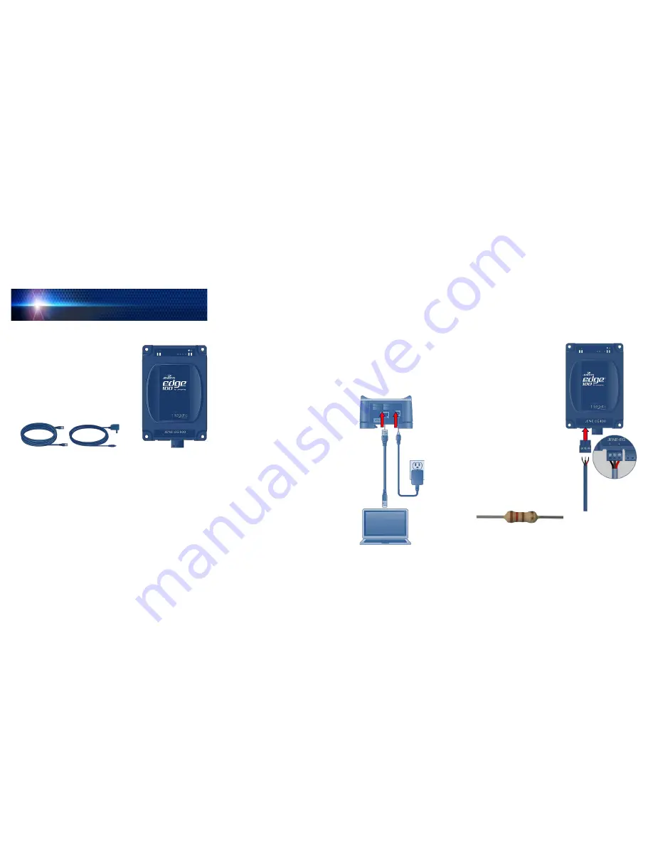
A 10/100-Mbit Ethernet connection is provided on the JENEsys-Edge 100.
This is an RJ-45 port. Use a standard Ethernet patch cable for connecting to an
Ethernet Hub or Switch or for connecting directly to your computer. The RJ-45
port has two LEDs. When the device is connected to a network, the amber L
INK
LED is lit and the green A
CTIVITY
LED flashes when activity occurs.
Step 1:
Connect one end of the Ethernet cable to your JENEsys-Edge 100’s
RJ-45 port and the other end to the internet port on your computer.
Step 2:
Connect the power adaptor to the JENEsys-Edge 100 and then plug
it into an outlet. Wait for the power LED and heartbeat LED to turn on.
If none of the LEDs turn on, make sure the barrel connector on the end
of the power adaptor is pressed firmly into
the JENEsys-Edge 100.
Step 3:
Temporarily change your computer’s
network settings so your IP address is in
the range:
192.168.1.1
to
192.168.1.254
(without using the JENEsys-Edge 100’s
default address as described in Step 4).
Make note of your computer’s current
network settings.
Step 4:
With ProBuilder 3.8.111 installed on your
computer, make a platform connection to the
JENEsys-Edge 100 using the factory default
IP address
(192.168.1.12n, where the last
numeral (n) matches the last numeral in the
JENEsys-Edge 100’s Host ID number)
, platform
daemon port (3011), and the following credentials:
Username:
tridium
Password:
niagara
Step 5:
Refer to the JENEsys-Edge 100’s
U
SER
G
UIDE
A
DDENDUM
and your local
copy of the N
IAGARA
AX
U
SER
G
UIDE
for
detailed instructions on how to configure the device using Niagara.
E
th
e
rn
e
t
Ca
b
le
P
o
w
er
A
da
pt
or
Preparing to Install the JENEsys-Edge 100
Decide where you want to place the JENEsys-Edge100. You can use wall
mounting screws
(not provided)
to mount the JENEsys-Edge 100 in an open
space or mount on a 35mm wide DIN rail utilizing the molded DIN rail slot located
on the base of the device.
Make sure the selected location is:
Not in direct sunlight or near a heater or heating vent.
Not cluttered or crowded. There should be at least 4 to 6 inches
(10-15 cm)
of clear space on the side where all of the network and power
connections are made.
Well ventilated
(especially if enclosed in a cabinet).
JENE-EG100
Estimated installation time: 5-10 minutes
Package Contents:
One JENEsys
®
-Edge 100
(JENE-EG100)
One 7ft Ethernet Cable
One AC Power Adaptor
One JENEsys-Edge 100 Installation
Guide
(this document)
One 3-Position Terminal Connector
One 3-Position Blank Terminal Connector
Ethernet Cable
Power Adaptor
JENEsys Edge 100
Connecting RS-485 Network to JENEsys-Edge 100
The RS-485 port uses a 3-position, screw terminal connector. The screw
terminals
(from left-to-right)
are shield, minus (-), and positive (+). The transmit
(Tx) and receive (Rx) LEDs located on the JENEsys-Edge 100 cover will flash
when there is network activity detected.
Step 1:
Unplug the left, 3-position screw
terminal connector from the
JENEsys-Edge 100.
Step 2:
Insert the positive wire from your
RS-485 network to the positive
terminal
(far right terminal)
on the
3-position, screw terminal connector
and tighten down the screw.
Step 3:
Insert the negative wire from your
RS-485 network to the negative
terminal
(center terminal)
on the
3-position, screw terminal connector
and tighten down the screw.
Step 4:
Insert the shield wire to the shield
terminal
(far left terminal)
on the
3-position, screw terminal connector
and tighten down the screw.
Step 5:
If located at the end of the network,
Lynxspring recommends installation
of a 120 ohm end-of-line resistor on
the + & - terminals.
Step 6:
Plug the 3-position, screw terminal
connector back into the RS-485
port on the JENEsys-Edge 100.
To RS-485 Network
RJ-45
Port
JENEsys
®
Edge 100
I
NSTALLATION
G
UIDE


