background image

VEHICLE IDENTIFICATION

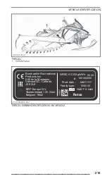
NRMM_E-TEC_MY20

TYPICAL

Rotax

10559

MXXXXXXX

XXXX

MM-YYYY

XXXXXX

SMB/P  V-####

Family type:

e13

NRSC H CO2 g/kWh:

#

Prod. date:

EN-516010559-DEC

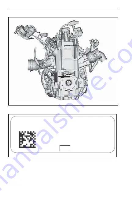
TYPICAL - NRMM IDENTIFICATION LABEL

Depending on your particular vehicle configuration, an additional
NRMM identification label may be installed on the tunnel, near the
chaincase.

218

_________________

Содержание RADIEN Crossover E-TEC Series

Страница 1: ...structions Includes Safety Vehicle and Maintenance Information Read this guide thoroughly It contains important safety information Minimum recommended age Operator 16 years old Keep this Operator s Gu...

Страница 2: ...me to familiarize yourself with your new vehicle Lynx products are manufactured by Bombardier Recreational Products Inc The following are trademarks of Bombardier Recreational Products Inc or its subs...

Страница 3: ...MODEL PACKAGE ENGINE Enduro 600R E TEC 600R E TEC Rave RE 3500 850 E TEC 600 EFI 3700 600R E TEC RE 3700 850 E TEC 3900 600R E TEC RE 3900 850 E TEC 600R E TEC Xterrain PRO 3900 850 E TEC ____________...

Страница 4: ...ekirja voi olla saatavissa omalla kielell si Tarkista j lleenmyyj lt tai k y osoitteessa www operatorsguides brp com Svenska Denna bok kan finnas tillg nglig p ditt spr k Kontakta din terf rs ljare el...

Страница 5: ...rnings contained in this Operator s Guide can result in SERIOUS INJURY or DEATH The proper functioning of a snowmobile depends in part on the surface on which it is driven See RIDING CONDITIONS AND YO...

Страница 6: ...nstructing others Note that this guide is available in several languages In the event of any discrepancy the English version shall prevail If you want to view and or print an extra copy of your Operat...

Страница 7: ...arrying a Passenger 26 Terrain Riding Variations 28 Environment 35 TRACTION ENHANCING PRODUCTS 38 Manoeuvrability 38 Acceleration 41 Braking 41 Important Safety Rules 41 Effects of Having a Studded Tr...

Страница 8: ...rd 92 Tools 95 Spare Drive Belt Holder 98 Upper Body Module 100 Side Panels 105 Electric Visor Jack Connector If Equipped 107 Mountain Strap If Equipped 108 Horn Button Not illustrated on vehicle 109...

Страница 9: ...nowmobile 140 TUNE YOUR RIDE 141 Rear Suspension Adjustments 142 Front Suspension Adjustments 149 Adjustment Tips According to Vehicle Behavior 155 Suspension Adjustment Table 156 VEHICLE TRANSPORTATI...

Страница 10: ...DIO FREQUENCY DIGITALLY ENCODED SECURITY SYSTEM RF D E S S KEY 223 SPECIFICATIONS ENGINE 224 SPECIFICATIONS VEHICLE 227 TROUBLE SHOOTING TROUBLESHOOTING GUIDELINES 240 MONITORING SYSTEM 243 Pilot Lamp...

Страница 11: ...TABLE OF CONTENTS CONTACT US 267 Asia 267 Europe 267 North America 268 Oceania 268 South America 268 CHANGE OF ADDRESS OWNERSHIP 269 __________________ 9...

Страница 12: ...TABLE OF CONTENTS 10 __________________...

Страница 13: ...SAFETY INFORMATION ____SAFETY INFORMATION ___ 11...

Страница 14: ...such as garages carports or barns Even if you try to venti late engine exhaust with fans or open windows and doors carbon monoxide can rapidly reach dangerous levels Never run the vehicle outdoors whe...

Страница 15: ...k of crashes or in juries and they can make the vehicle illegal Tunnel accessories must be loaded onto vehicle as per instructions provided for each accessories Accessory passenger seats approved by B...

Страница 16: ...ation of any snow mobile Study your operator s guide paying particular attention to cautions and warnings Join your local snowmobile club its social activities and trail systems are planned for both f...

Страница 17: ...nd regulations pertaining to the safe use and operation of snowmobiles It is your re sponsibility as a snowmobiler to learn and obey these laws and regulations Respect and observance will result in sa...

Страница 18: ...bile Give a wide berth to telephone poles or posts Hidden wires unseen from a distance can cause serious acci dents Always wear an approved safety helmet eye protection and a face shield This also app...

Страница 19: ...ngine cut off switch while applying brake Always engage parking brake when vehicle is not in use Never run the engine in a non ventilated area and or if vehicle is left unattended Electric start model...

Страница 20: ...this guide Make sure that you are able to achieve a stable stance both feet resting positively on the footboards of footrests with good grip and that you are able to hold on firmly to the handholds W...

Страница 21: ...for your dealer to verify if your snowmobile is included in any safety campaign We also urge you to visit your authorized Lynx dealer in a timely manner if you become aware of any safety related campa...

Страница 22: ...re the brake control lever touches the handlebar grip It must fully return when released 8 Apply parking brake and check if it operates properly Leave park ing brake applied 9 Inspect drive belt condi...

Страница 23: ...level and no leaks STORAGE COMPARTMENT Check for proper latching and no heavy or breakable objects TRACK Check condition and remove snow or ice For studded tracks refer to TRACTION ENHANCING PRODUCTS...

Страница 24: ...nd reduce injury A stocking type cap bala clava and face mask should always be carried or worn Goggles or a face shield that attach to the helmet are indispensable Hands should be protected by a pair...

Страница 25: ...on Operator and passenger must never attempt this maneuvering by placing feet outside of the vehicle Experience will teach you how much lean to put into turns at different speeds and how much you will...

Страница 26: ...i sitting position with the body off the seat and the feet under the body in a sort of squatting posture thus allowing the legs to absorb the shocks when traveling over uneven terrain Avoid abrupt sto...

Страница 27: ...he opposite knee on the seat Avoid abrupt stops fmo2008 003 003 Standing Place both feet on the running boards Knees should be flexed to absorb the shock from surface bumps This is an effective positi...

Страница 28: ...an unexpected acceleration WARNING Unexpected acceleration when snowmobile operates in re verse can cause a loss of control Carrying a Passenger Certain snowmobiles are designed for an operator only...

Страница 29: ...must right away inform the operator to slow down or stop Riding with a passenger on board is different than riding alone The operator has the benefit of knowing what will be the next maneuver and is a...

Страница 30: ...m grip and is prop erly positioned with his feet on the running boards Terrain Riding Variations Groomed Trail On a maintained trail sitting is the most preferred riding position Do not race and above...

Страница 31: ...dents about the ice condition inlets outlets springs fast moving currents or other hazards Never attempt to operate your snowmobile on ice that may be too weak to support you and the vehicle Operating...

Страница 32: ...chine to run downhill with the engine operating If a higher than safe speed is reached slow down by braking but apply the brake with frequent light pressure Never jam the brake and lock the track Side...

Страница 33: ...your tracks get off the ice immediately Ice and water can be thrown rearward into the path of a following snowmobile Getting a vehicle out of a slush area is strenuous and in some cases impossible Fog...

Страница 34: ...s have been caused by running into wires in the fields guy wires next to poles and roads and into chains and wires used as road closures Slow speeds are a must Obstacles and Jumping Unplanned jumps of...

Страница 35: ...ow you can climb without difficulty Use the standing position and proceed with only as much speed needed to crest the bank Stop completely at the top of the bank and wait for all traffic to clear Judg...

Страница 36: ...that all members of the party are aware of the proposed route and desti nation Make certain that you are carrying all necessary tools and equipment and that you have sufficient fuel to complete the tr...

Страница 37: ...me So the next time you hit the trails on a cool crisp and clear winter day we ask you to remember that you are paving the way for the future of our sport Help us lead it down the right path From all...

Страница 38: ...n from the Forest Service or from other public land agencies Learn the rules and follow them and that goes for speed limits too Avoid running over young trees shrubs and grasses and don t cut wood On...

Страница 39: ...ing will preserve this opportunity and will make it possible for us to expose others to the beauty of winter and the unique thrill of our sport Light Treading will help our sport to grow Finally Ligh...

Страница 40: ...avior particularly in terms of manoeuvrability acceleration and braking Using traction enhancing products gives a better grip on packed snow and ice but has no noticeable effect on soft snow For this...

Страница 41: ...roducts the snowmobile may tend to oversteer or understeer which could lead to a loss of control Oversteering In certain conditions using more aggressive ski carbide runners with out studs on the rear...

Страница 42: ...A33A33A UNDERSTEERING Controlled Driving A balanced combination of carbide ski runners and studs on the track ensures adequate control and better handling see illustration A33A34A CONTROLLED DRIVING 4...

Страница 43: ...ll give you better braking capacity on packed snow or ice but will have no noticeable effect on soft snow Braking may thus vary suddenly under certain conditions Be sure to use restraint in braking to...

Страница 44: ...ticular model Damage to the electrical wiring or perforation of the heat exchangers are potential hazards that could cause the engine to overheat and be severely damaged WARNING If tunnel protectors a...

Страница 45: ...cial studs Never use studs that exceed the height of your snowmobile s track profile by more than 9 5 mm 3 8 in 2 A33A32A 3 1 4 INSTALLATION OF STUDS 1 Stud size 2 Penetration range 6 4 mm to 9 5 mm 1...

Страница 46: ...s triangles and circles See the warning molded into the track surface to know which one to use Never stud a track with a profile of 35 mm 1 3 8 in or more The number of studs installed must always per...

Страница 47: ...Broken studs studded tracks Bent studs studded tracks Missing studs Studs that are torn off the track Missing track guide s Also ensure that studs nut are tighten to the recommended torque On approved...

Страница 48: ...performance fuel and oil economy that only the E TEC technology delivers Cher client Votre nouveau moteur technologie E TEC a une p riode de rodage contr l e automatiquement qui assurera une performa...

Страница 49: ...SEA LEVEL Operating above 2000 ft requires calibration parts and adjustment For more details REFER to your Operator s Guide that came with your snowmobile or see your authorized Ski Doo dealer INCORR...

Страница 50: ...cle and they should be consid ered permanent parts of the vehicle If missing or damaged the de cals can be replaced free of charge See an authorized Lynx dealer NOTE In the event of any discrepancy be...

Страница 51: ...e fuel vapors may ignite in presence of a spark creating a fire hazard Toujours d brancher les connecteurs lectriques des deux injecteurs d essence avant de v rifier la production d tincelles Autremen...

Страница 52: ...or catch your clothing NOTICE Drive pulley bolt recommended torque 115 N m to 125 N m 85 lbf ft to 92 lbf ft Not applying the recommended torque may result in a major failure of the drive pulley and t...

Страница 53: ...is could be projected causing severe injuries To remove packed snow ice stop engine lift and hold vehicle on the side and use wrench tool on the belt guard NEVER sit in cargo area 516009925 EN_5160099...

Страница 54: ...SAFETY INFORMATION ON THE VEHICLE Label 5 CAUTION Hot surface 516009922 EN_516009922_DEC LABEL 5 52 ____SAFETY INFORMATION____...

Страница 55: ...ORMATION ON THE VEHICLE Label 6 WARNING This guard must ALWAYS be in place when engine is running 516009932 EN_516009932_DEC LABEL 6 L Label 7 516009921_RH EN_516009921_DEC LABEL 7 ____SAFETY INFORMAT...

Страница 56: ...SAFETY INFORMATION ON THE VEHICLE Label 8 mmo2008 003 007 LABEL 8 54 ____SAFETY INFORMATION____...

Страница 57: ...ATION ON THE VEHICLE Label 9 WARNING NEVER exceed maximum load capacity in cargo area MAXIMUM REAR LOAD 15 8 kg 34 8 lb Refer to Operator s Guide 516009924 8 EN_516009924_DEC LABEL 9 ____SAFETY INFORM...

Страница 58: ...SAFETY INFORMATION ON THE VEHICLE Label 10 WARNING Beware of hot parts 516009935 EN_516009935_DEC LABEL 10 56 ____SAFETY INFORMATION____...

Страница 59: ...ON THE VEHICLE Label 11 Rave Models WARNING NEVER stud the track unless it has been approved for studs Refer to the operator s guide for more details EN 516009986 DEC LABEL 11 RAVE MODELS ____SAFETY...

Страница 60: ...veloped and validated using the BRP XPSTM approved lubricant BRP recommends the use of its XPSTM approved lubricant or equivalent Damages caused by oil which is not suitable for this engine may not be...

Страница 61: ...C_a LABEL 2 XTERRAIN MODELS 516009267 WITHOUT FORCE 30 mm WITH FORCE 7 3kg 45 mm EN 516009267 DEC_a LABEL 2 RAVE AND MODELS L Label 3 Install Suspension adjustment tool 1st illustrated Red on label In...

Страница 62: ...SAFETY INFORMATION ON THE VEHICLE 516009955 EN_516009955_DEC LABEL 3 DEC 513033942 EN FR ON FUEL CAP ON 600 EFI ENGINE IN COUNTRIES USING RON OCTANE RATINGS 60 ____SAFETY INFORMATION____...

Страница 63: ...SAFETY INFORMATION ON THE VEHICLE DEC 513033943 EN FR ON FUEL CAP ON E TEC ENFINES IN COUNTRIES USING RON OCTANE RATINGS ____SAFETY INFORMATION ___ 61...

Страница 64: ...SAFETY INFORMATION ON THE VEHICLE This page is intentionally blank 62 ____SAFETY INFORMATION____...

Страница 65: ...VEHICLE INFORMATION __________________ 63...

Страница 66: ...on on vehicle safety labels refer to SAFETY INFORMATION ON THE VEHICLE Handlebar The handlebar controls the steering of the snowmobile As the han dlebar is rotated to right or left the skis are turned...

Страница 67: ...hrottle Lever 619900989 005 Throttle lever is located on the RH side of handlebar Designed to be thumb activated When squeezed it increases the engine speed When released engine speed returns automati...

Страница 68: ...520002353 007_a 1 To accelerate 2 To decelerate WARNING Test the throttle lever operation each time before starting the engine The lever must return to the rest position once released Otherwise do not...

Страница 69: ...lever is located on the LH side of handlebar When squeezed brake is applied When released it automatically returns to the rest Braking effect is proportional to the pressure applied on the lever and...

Страница 70: ...01_a TYPICAL 1 Brake lever 2 Apply brake Parking Brake Lever Parking brake lever is located on the LH side of handlebar Parking brake should be used whenever snowmobile is parked 520001496 001_b TYPIC...

Страница 71: ...and cause loss of braking capacity and or fire To Engage Parking Brake Apply and hold brake then lock brake lever using the parking brake lever as shown mmo2009 005 006_a TYPICAL ENGAGE MECHANISM Step...

Страница 72: ...cap must be securely snapped on the engine cut off switch to allow vehicle operation NOTE After engine starting 2 short beeps should be heard if a programmed D E S S key tether cord cap is correctly s...

Страница 73: ...cord cap to allow vehicle operation If another tether cord is used without programming the D E S S the engine will start but will not reach drive pulley engagement speed to move vehicle Make sure the...

Страница 74: ...0989 006 The emergency engine stop switch is located on the RH side of han dlebar Push pull type switch To stop the engine in an emergency select OFF position down and simultaneously apply the brake T...

Страница 75: ...CONTROLS INSTRUMENTS AND EQUIPMENT mmo2016 008 202_a OFF POSITION To allow engine starting the switch must be in the ON position UP __________________ 73...

Страница 76: ...outing and whenever stopping the engine thereafter This engine stopping procedure will become a reflex and will prepare operators for emergency situations requiring its use WARNING If the switch has...

Страница 77: ...OLS INSTRUMENTS AND EQUIPMENT Console Switches if equipped Ignition Key 619900989 001 Turn the ignition key to start the engine Refer to ENGINE STARTING PROCEDURE in BASIC PROCEDURES _________________...

Страница 78: ...S AND EQUIPMENT Headlights Dimmer Switch 619900989 003 Press to select HI or LOW beam Lights are automatically ON when the engine is running 520001496 004_a SWITCH ON CONSOLE 1 High beam 2 Low beam 76...

Страница 79: ...tch on console controls simultaneously the handlebar grips and throttle lever heat intensity The balance between the tempera ture of the throttle lever and the grips can be adjusted Contact an authori...

Страница 80: ...eat 2 Decrease heat The heating intensity is displayed via the digital display 619900974 701 HEATED GRIPS DISPLAY Heated grips will be in OFF position when there are no bars displayed on the gauge Whe...

Страница 81: ...layed on the gauge When the switch is released display will return to fuel level Ignition Switch if equipped 619900989 001 Turn the ignition key to start the engine Refer to ENGINE STARTING PROCEDURE...

Страница 82: ...1496 002_a 1 Start RER button On SHOT and electric start models press to start engine Once engine is started press to engage the electronic reverse Refer to BASIC PROCEDURES for instructions on how to...

Страница 83: ...CONTROLS INSTRUMENTS AND EQUIPMENT Multifunction Switch if equipped 619900996 010 TYPICAL Multifunction switch is located on the LH side of handlebar __________________ 81...

Страница 84: ...to ENGINE STARTING PROCEDURE in BASIC PROCEDURES Once engine is started press to engage the electronic reverse Re fer to REVERSE RER in BASIC PROCEDURES for procedure Headlights Dimmer Switch Press to...

Страница 85: ..._d TYPICAL VARIABLE INTENSITY 1 Heated grip switch 2 Increase heat 3 Decrease heat The heating intensity is displayed via the digital display NOTE There are ten intensity settings When released displa...

Страница 86: ...ess heat Heated grips will be in OFF position when there are no bars displayed on the gauge Heated Throttle Lever Switch NOTE Under 2000 RPM heated throttle lever will be limited at 50 Depress switch...

Страница 87: ...rottle lever switch 2 Increase heat 3 Decrease heat NOTE The heating intensity is displayed via the multifunction dis play with the activation of the throttle lever switch There are ten intensity sett...

Страница 88: ...ISPLAY 1 Heated throttle icon 2 More heat 3 Less heat Heated throttle lever will be in OFF position when there are no bars displayed on the gauge Menu Set Button This button is used to manage the info...

Страница 89: ...STRUMENTS AND EQUIPMENT mmo2014 004 001_f TYPICAL MULTIFUNCTION GAUGE 1 Menu function 2 SET function refer to GAUGE for complete informations Rewind Starter Handle if equipped 619900989 007 __________...

Страница 90: ...y the rewind starter is 80 N m 59 lbf ft The maximum force that can be exerted on the on the rope is 2 200 N 494 6 lbf Storage Compartment A storage compartment is located at the front of the vehicle...

Страница 91: ...l backwards while holding front part up Slide seat rearwards to remove it 619900979 005 TYPICAL Step 1 Pull up Step 2 Pull backwards Seat Installation NOTICE Riding the vehicle with any objects betwee...

Страница 92: ...obile requires manual lifting CAUTION Beware of injuries by using proper lifting tech niques notably using your legs force Do not attempt to lift the rear of vehicle if it is above your limits Use app...

Страница 93: ...CONTROLS INSTRUMENTS AND EQUIPMENT 619900974 005 HEAVY DUTY MODELS 619900974 007 TYPICAL 1 Rear bumper __________________ 91...

Страница 94: ...de panels opened or removed NEVER attempt to make adjustments to moving parts while engine is running NOTE Belt guard is purposely made slightly oversize to maintain tension on its pins and retainers...

Страница 95: ...3_a TYPICAL Lift rear portion of guard then release from front tab Drive Belt Guard Installation Insert belt guard tab in front support slot 219100985 017 001_a Push drive belt guard toward engine the...

Страница 96: ...CONTROLS INSTRUMENTS AND EQUIPMENT 219100985 017 002_a 219100985 017 003_a Position the rear portion of the belt guard over the retainer and secure it using the retaining pin 94 __________________...

Страница 97: ...97 003_a Tools A part of the drive belt guard is designed to hold the tools allowing for basic maintenance The tools are supplied with the vehicle They should always be installed in their proper locat...

Страница 98: ...and headlight adjustment tool Install in the following sequence CAUTION Make sure tools are secured properly Tools may detach and cause damage to rotating parts 1 Slide the suspension adjustment tool...

Страница 99: ...ND EQUIPMENT 520002104 500 3 Slide the Pulley expander and headlight adjustment tool short end into hole 520001798 008 PULLEY EXPANDER AND HEADLIGHT ADJUSTMENT TOOL 4 Rotate and clip long end in place...

Страница 100: ...4 501 Spare Drive Belt Holder A spare drive belt can be stored in a holder located on the drive belt guard NOTE The spare drive belt is not supplied with the snowmobile Position spare drive belt into...

Страница 101: ...CONTROLS INSTRUMENTS AND EQUIPMENT 520001897 002_a TYPICAL 1 Drive belt guard 2 Slot Secure in place by sliding it behind the tabs 520001897 002_b TYPICAL __________________ 99...

Страница 102: ...CONTROLS INSTRUMENTS AND EQUIPMENT Upper Body Module Upper Body Module Removal 1 Remove the windshield 2 Open the storage compartment 520002353 017_a 100 _________________...

Страница 103: ...CONTROLS INSTRUMENTS AND EQUIPMENT 3 Remove the gauge support retaining screws 619900974 008 TYPICAL _________________ 101...

Страница 104: ...gauge support then slide it forward to remove it 619900974 009 5 Disconnect gauge connector and remove support 6 Lift storage compartement and disconnect 12V power outlet con nectors before removing...

Страница 105: ...AND EQUIPMENT 520002353 019_a 7 Disconnect the MAPTS and headlight connectors mmr2017 051 012 TYPICAL 8 Remove both side panels Refer to SIDE PANELS in this section 9 Loosen the air intake duct clamp...

Страница 106: ...emove the upper body module retaining screws on both sides 619900968 705 11 Remove the upper body module 11 1 Grab the upper body module in the gauge support sec tion 11 2 Pull the module forward 11 3...

Страница 107: ...the hood TIGHTENING TORQUE Upper body screws 2 3 N m 0 2 N m 20 lbf in 2 lbf in 6 Connect the manifold air pressure and temperature sensor MAPTS connector 7 Connect the headlight connectors 8 Install...

Страница 108: ...CONTROLS INSTRUMENTS AND EQUIPMENT 619900968 708 TYPICAL 1 Unhook 2 Turn 219100889 054 002_a TYPICAL When closing panel make sure latches are locked securely 106 _________________...

Страница 109: ...Open side panel Lift the side panel to disengage the tabs 219100889 054 003 Electric Visor Jack Connector If Equipped An electric visor can be connected to the jack connector A stress re lief extensi...

Страница 110: ...bile is stuck in a slanted position On an excep tional basis it can be used at very slow speed only when standing on the right running board to bring the vehicle back on its desired path When riding b...

Страница 111: ...se while riding at speed Steering control is highly re duced and brake control is not possible Horn Button Not illustrated on vehicle For vehicles sold in Finland Press on the horn button mounted on h...

Страница 112: ...y 619900974 706 Lower Display 619900974 700 May display the following RPM Speed Engine Temperature Fuel Statistics Settings Messages Outside temperature if equipped Use LOWER button to change the disp...

Страница 113: ...eset When the SPEED display is chosen the RPM is shown in the TRIP display Left Lateral Display 619900974 701 The left lateral display includes Fuel level indicator Heated Grip level Right Lateral Dis...

Страница 114: ...he vehicle speed in Km h or MPH Trip Display 619900974 705 This display shows trip informations Cumulative distance odometer Trip A hours Trip A distance Km or mph Vehicle hour meter Clock If battery...

Страница 115: ...amp for further information NOTE Some warning indicators appear in the display of the multi function gauge and function the same as an indicator lamp but do not display when starting the vehicle Tellt...

Страница 116: ...NGE Turn on Malfunction of the vehicle emissions control system Blink Engine problems the limp home mode is activated Have the vehicle serviced immediately Settings Setup 520002114 102 1 Upper button...

Страница 117: ...display 2 Push and hold LOWER button for 1 second 3 Press LOWER button to select 12 00 AM PM or 24 00 time base 4 Push and hold LOWER button to acknowledge selection 5 Press LOWER button to change hou...

Страница 118: ...ifunction Display 619900975 500 Lower Display 619900975 501 May display the following Settings Messages The SPEED display shows the Maximum and the averaged speed Hold MENU button for 3 seconds to res...

Страница 119: ...teral Display 619900975 502 The left lateral display includes Fuel level indicator Heated Grip level Trip distance A and B Km or mph Cumulative hours Speed RPM Odometer Right Lateral Display 619900975...

Страница 120: ...SPLAY The right lateral display includes Engine Temperature Heated throttle indicator Clock Central Display 619900975 504 Display the vehicle speed in Km h or MPH or the RPMs Refer to SETTINGS 118 ___...

Страница 121: ...minate when starting the vehicle to make sure they work If any lamps remain on after starting the vehicle refer to the respective system warning lamp for further information NOTE Some warning indicato...

Страница 122: ...m with the electrical system RED Low engine oil pressure if applicable ORANGE Low fuel level ORANGE Turn on Malfunction of the vehicle emissions control system Blink Engine problems the limp home mode...

Страница 123: ...display by using the MENU M button on the multifunction switch 2 While the desired display is flashing navigate through the display by using the SET S button on the multifunction switch Once the desir...

Страница 124: ...NU button to select clock display 2 Push and hold MENU button for 1 second 3 Press MENU button to select 12 00 AM PM or 24 00 time base 4 Push and hold MENU button or OK button to acknowledge selec ti...

Страница 125: ...t in the following problems in the fuel system components Starting and operating difficulties Deterioration of rubber or plastic parts Corrosion of metal parts Damage to internal engine parts Inspect...

Страница 126: ...damages may occur with the use of an inadequate fuel NOTICE Do NOT use fuel from fuel pumps labeled E85 Use of fuel labeled E15 is prohibited by U S EPA Regulations Vehicle Fueling Procedure WARNING A...

Страница 127: ...tank cap 4 Insert the spout into the filler neck 5 Pour fuel slowly so that air can escape from the tank and prevent fuel flow back Be careful not to spill fuel 6 Stop filling when the fuel reaches th...

Страница 128: ...FUEL WARNING Always wipe off any small fuel spillage from the vehicle If a major spillage occurs remove side panels to remove fuel va pors from engine compartment before starting 126 _________________...

Страница 129: ...hetic Blend Oil semi synthetic 600R E TEC 850 E TEC 2T E TEC Synthetic Oil full synthetic IF THE RECOMMENDED XPS ENGINE OIL IS NOT AVAILABLE Use a 2 stroke lubricant designed for snowmobiles meeting o...

Страница 130: ...indicates 3 8 and 1 2 of the total amount of oil NOTICE Check level and refill every time you refuel To Add Injection Oil Remove injection oil reservoir cap Add injection oil NOTE Do not overfill Wip...

Страница 131: ...INJECTION OIL 520002095 012_a Reinstall cap NOTICE Do not overtighten WARNING Wipe off any oil spills Oil is highly flammable when heated _________________ 129...

Страница 132: ...rameters The duration is based on fuel volume It will take approximately two fuel tanks to complete the break in During this period The engine performance and behavior will not be optimal The fuel and...

Страница 133: ...le slowly until a resistance is felt then hold handle firmly and pull vigorously to start engine NOTE The maximum torque that can be transmitted to the engine by the rewind starter is 80 N m 59 lbf ft...

Страница 134: ...UIPMENT WARNING Do not wind starting rope around your hand Hold rope by the handle only Do not start the engine by the drive pulley unless it is a true emergency situation Have the snowmobile repaired...

Страница 135: ...1 Rope crossed 2 Rope to be winded 3 Rope end Wind rope two turns counterclockwise tightly around the drive pulley where shown Pull the rope using a sharp crisp pull so the rope comes free of the dri...

Страница 136: ...obile repaired Vehicle Warm Up Before every ride vehicle has to be warmed up as follows 1 Start engine as explained in ENGINE STARTING PROCEDURE above 2 Allow engine to warm up one or two minutes at i...

Страница 137: ...ake sure tether cord cap is removed before standing in front the vehicle getting close to the track or rear suspension com ponents NOTE Warm up is electronically controlled During this period up to 10...

Страница 138: ...throttle lever WARNING Engaging the reverse mode is done by depressing the RER button when the engine is running Wait until the reverse alarm sounds and the RER pilot lamp comes on in the digital gaug...

Страница 139: ...Release throttle lever and wait until engine has returned to idle speed 600 EFI Engine Turn the ignition key counterclockwise in OFF position and pull off the tether cord cap E TEC Engine Shut off th...

Страница 140: ...nes provides the optimum air fuel ratio for all temperatures Hard Packed Snow Some models covered in this guide are built for deep snow condi tions and should never be used during prolonged time in ma...

Страница 141: ...recommended to ride these models in trail or hard snow conditions it is highly recommended to combine idler wheels with ice scratchers if the vehicle is used in those conditions IMPORTANT Track lug se...

Страница 142: ...wmobile refer to DRIVE BELT in MAINTENANCE PROCEDURES and tow at moderate speed NOTICE Always remove the drive belt of the snowmobile that is to be towed to prevent damage to its belt and drive system...

Страница 143: ...are lifting stress If a lifting device is not used use proper lift ing techniques notably using your legs force Do not attempt to lift the front or rear of vehicle if it is above your limits Support f...

Страница 144: ...if necessary Stopper Strap Stopper strap length has an effect on the amount of weight the cen ter spring has to carry especially during acceleration therefore on the front end uplift Stopper strap len...

Страница 145: ...at which the track rides on the snow Operator s familiarity with the various adjustments as well as snow conditions will dictate the most efficient combination Generally a longer stopper strap settin...

Страница 146: ...effect on steering effort handling and bump absorption Also since center spring preload adjustment puts more or less pres sure on the front of the track it has an effect on the performance in deep sno...

Страница 147: ...lso adjusting rear spring preload shifts more or less weight to the snowmobile front end As a result more or less weight is applied to the skis This has an effect on performance in deep snow steering...

Страница 148: ...bump absorption capability Lighter steering Decreasing preload Better deep snow performance and handling Refer to the following to determine if preload is correct mmr2015 142 003_a TYPICAL PROPER ADJ...

Страница 149: ...ng refer to SUSPENSION ADJUSTMENT TABLE To adjust unscrew the locking ring then turn the adjustment ring to set the spring preload When the desired preload is set tighten the locking ring against the...

Страница 150: ...High speed compression adjuster hexagonal 2 Low speed compression adjuster slotted TURNING ACTION RESULT ON BIG AND SMALL BUMPS Clockwise Increasing compression damping force Firmer compression dampin...

Страница 151: ...rebound damping force Softer rebound damping faster extension speed NOTE In repetitive short small bumps ripple it is recommended to use a lower rebound damping setting Front Suspension Adjustments Sk...

Страница 152: ...snow NOTE It is recommended to only use middle position 619900934 013_a 1 Spacers 2 Axle 3 Stopper 4 Screw 5 Washer 6 Nut TIGHTENING TORQUE Ski nut 31 5 N m 3 5 N m 23 lbf ft 3 lbf ft Front Springs Fr...

Страница 153: ...creasing preload More bump absorption capability Softer front suspension Lower front end Lighter steering Decreasing preload Less bump absorption capability mmo2010 003 027_a CAM TYPE HPG SHOCK ABSORB...

Страница 154: ...ession Damping Low speed compression damping controls how the shock absorber reacts to a low suspension velocity slow compression strokes in most cases when riding at lower speeds High speed compressi...

Страница 155: ...ACTION RESULT ON BIG AND SMALL BUMPS Clockwise Increasing compression damping force Firmer compression damping Counter Clockwise Decreasing compression damping force Softer compression damping Reboun...

Страница 156: ...se Increasing rebound damping force Firmer rebound damping slower extension speed Counter Clockwise Decreasing rebound damping force Softer rebound damping faster extension speed NOTE In repetitive sh...

Страница 157: ...ation Reduce rear spring preload Lengthen limiter strap Too much ski lift during cornering or acceleration Shorten limiter strap Increase rear spring preload Rear of snowmobile seems too stiff Reduce...

Страница 158: ...ap Track spins too much at start Lengthen limiter strap Ski diving in deep snow Install ski tip enlarger Suspension Adjustment Table NOTE Clicks and turns counted from closed position FRONT SPRING SHO...

Страница 159: ...s 2 5 2 0 5 Rebound Clicks 10 8 6 Spring preload mm With stopper strap removed 2 2 2 STOPPER STRAP POSITION XTERRAIN POSITION XTRIM RE RE PRO STD 1 Best comfort Longest travel in center arm suspension...

Страница 160: ...STANDARD SPORT Low speed compression Clicks 20 15 5 High speed compression Turns 2 5 2 0 5 Rebound Clicks 10 8 6 Spring preload mm With stopper strap removed 7 7 7 NOTE For E Start models and or on L...

Страница 161: ...over a trailer Anchor your vehicle securely front and rear even on short hauls Be certain all equipment is securely fastened Cover your snowmobile when trailering to prevent road grime from causing da...

Страница 162: ...VEHICLE TRANSPORTATION This page is intentionally blank 160 _________________...

Страница 163: ...MAINTENANCE _________________ 161...

Страница 164: ...procedures can make it unsafe to oper ate DURING THE FIRST 1 500 KM 1 000 MI Adjust drive chain after the first 75 km 50 mi Adjust drive chain every 500 km 300 mi Adjust and align track after the fir...

Страница 165: ...ension Lubricate whenever the vehicle is used in wet conditions rain puddles Inspect exhaust system and check for leaks Tighten exhaust manifold screws to specified torque Inspect fuel lines oil lines...

Страница 166: ...incase oil Inspect engine rubber mounts EVERY 3 YEARS OR 10 000 KM 6 000 MI WHICHEVER COMES FIRST Replace spark plugs E TEC Inspect oil injection pump strainer and clean if needed Clean and inspect 3D...

Страница 167: ...king fasteners etc when undergoing disassembly assembly always replace with a new one Engine Coolant WARNING Never open coolant tank cap when engine is hot Engine Coolant level Verification Open the R...

Страница 168: ...g cor rosion inhibitors specifically for internal combustion aluminum engines Exhaust System Exhaust System Verification The muffler tail pipe should be centered with the exit hole in the bot tom pan...

Страница 169: ...id Recommended Fluid Use only DOT 4 brake fluid from a sealed container An opened con tainer may be contaminated or may have absorbed moisture from the air WARNING Use only DOT 4 brake fluid from a se...

Страница 170: ...MAINTENANCE PROCEDURES mmo2014 004 001_g TYPICAL 1 Brake fluid reservoir 168 _________________...

Страница 171: ...of contact skin wash thoroughly In case of contact with the eyes immediately rinse with plenty of water for at least 10 minutes and then consult a doctor imme diately Chaincase Oil Recommended Chainc...

Страница 172: ...ll times Damages caused by oil which is not suitable for the chaincase will not be covered by the BRP limited warranty Chaincase Oil Level Verification With the vehicle on a level surface check the oi...

Страница 173: ...emove the drain plug located at the bottom of gearbox 520002131 012 5 Wait a while to allow all oil to drain out of gearbox 6 Install drain plug and tighten to specification TIGHTENING TORQUE Gearbox...

Страница 174: ...K PLUG 3 Remove the filler cap 520001663 010_a TYPICAL TOP OF CHAINCASE 1 Filler cap 4 Pour recommended oil in the filler hole until oil comes out by the check plug hole 5 Reinstall check plug and tig...

Страница 175: ...NTROLS INSTRUMENTS AND EQUIPMENT Drive Chain Adjustment Using the Torx end of the driven pulley expander GENTLY turn ten sioner clockwise to eliminate the play 520001798 006_a TYPICAL Do not force the...

Страница 176: ...riod burred or rusty sheave oil on belt or distorted spare belt Contact an authorized Lynx dealer Drive Belt Replacement Drive Belt Removal 1 Remove tether cord cap from engine cut off switch 2 Remove...

Страница 177: ...rows in the direction of rotation mmo2011 002 006_a 1 To be pointed in the direction of rotation 3 Unscrew and remove the driven pulley expander from the pulley 4 Rotate the driven pulley several time...

Страница 178: ...e cut off switch 2 Remove drive belt guard 3 Loosen the clamping bolt mmo2011 003 010_a 1 Adjuster hub 2 Clamping bolt 4 Using the suspension adjustment tool provided turn the ring 1 4 turn at a time...

Страница 179: ...00 EFI Repeat step 4 until the drive belt outer surface is even with the driven pulley edge mmo2012 005 981_a 600 EFI PRELIMINARY SETTING 1 Drive belt outer surface is even with the driven pulley edge...

Страница 180: ...edge mmo2012 006 905_a TYPICAL PRELIMINARY SETTING 1 Lowest portion of cogs even with driven pulley external edge NOTE Turning the ring counterclockwise lowers the drive belt in the pulley Turning th...

Страница 181: ...ting the engine the vehicle could creep indicating that the drive belt is too tight If the vehicle creeps lower the drive belt height from the preliminary setting Repeat procedure until creeping stops...

Страница 182: ...les The drive pulley is factory calibrated to transmit maximum engine power at a predefined RPM Factors such as ambient temperature altitude or surface condition may vary this critical engine RPM thus...

Страница 183: ...lley guard 2 Locate the cam and the pivot screw on the drive pulley 520001496 020_a TYPICAL 1 Cam 2 Pivot screw The cam position is identified as follows Positions 1 2 4 and 5 are numbered Position 3...

Страница 184: ...EDURES mmc2016 001 118_b 1 Numbered position 2 Position 3 Notch 3 Pointers To adjust proceed as follows for all 3 cams 3 Using the Allen end of the driven pulley expander loosen the pivot screw 182 __...

Страница 185: ...MAINTENANCE PROCEDURES mmc2016 001 116_a 1 Pivot screw 4 Move the right lever aside to be able to turn the cam 5 Turn cam to the desired position _________________ 183...

Страница 186: ...ROCEDURES mmc2016 001 117_a 1 Desired cam position here 2 6 Tighten the pivot screw TIGHTENING TORQUE Pivot 8 N m 1 N m 71 lbf in 9 lbf in NOTICE Always adjust all 3 cams to the same setting 184 _____...

Страница 187: ...er cord cap from engine cut off switch Lift the rear of the snowmobile and support it with a wide base snow mobile mechanical stand with a rear deflector panel With the engine off rotate the track by...

Страница 188: ...commended torque On approved studded tracks replace broken or damaged studs im mediately If your track shows signs of deterioration it must be re placed immediately When in doubt ask your dealer WARNI...

Страница 189: ...ds out of the tunnel with tremendous force possibly resulting in the loss of a leg or other serious injury Track Tension Verification NOTE Ride the snowmobile in snow about 15 to 20 minutes prior to a...

Страница 190: ...ecification 6 Place upper O ring to 0 kgf 0 lbf 7 Position the tensiometer on track halfway between front and rear idler wheels 8 Push the tensiometer downwards until bottom O ring deflection set earl...

Страница 191: ...O ring on the tensiometer mmr2009 133 003_a TYPICAL LOAD READING 1 Upper O ring 10 Load reading must be as per the following table Rave Enduro 3300 Xtrim RE 3500 and Rave RE models TRACK ADJUSTMENT S...

Страница 192: ...is not in accordance with the specification adjust track tension Refer to TRACK TENSION ADJUSTMENT Track Tension Adjustment 1 Remove tether cord cap from engine cut off switch 2 Lift rear of vehicle...

Страница 193: ...n or loosen the adjustment screws 6 If correct tension is unattainable contact an authorized Lynx dealer 7 Retighten the rear axle nut to specification TIGHTENING TORQUE Rear idler wheel retaining nut...

Страница 194: ...e debris damaged or loose studs pieces of torn track or an entire severed track to be violently thrown backwards out of the tunnel with tremendous force 1 Lift rear of vehicle and support it off the g...

Страница 195: ...safe place away from the trail 4 3 Loosen the rear axle nut 4 4 Tighten adjustment screw on side where the slider shoe is the farthest from the track insert guides A01F0BA 1 2 3 1 1 Guides 2 Slider s...

Страница 196: ...ng on ice or sanded snow will cre ate excessive heat build up and cause premature slider shoe wear Suspension Stopper Strap Condition Inspect stopper strap for wear and cracks bolt and nut for tightne...

Страница 197: ...nts ski bolts ski legs etc If necessary contact an authorized Lynx dealer Skis Wear and Condition of Skis and Runners Check the condition of the skis and ski runner carbides If worn con tact an author...

Страница 198: ...MAINTENANCE PROCEDURES Fuses Location 520001663 024_a TYPICAL 1 Fuse block Unlock fuse block from its cover 600 EFI Engine 520002353 021 FUSE BOX 196 _________________...

Страница 199: ...ATION RY1 Main RY2 Lights Accessory E TEC Engine FUSE IDENTIFICATION AMPERAGE RATING F1 Start RER 5 A F2 Accessories Loads 25 A F3 Battery 30 A F4 Cluster 15 A Fuse Inspection Check fuse condition and...

Страница 200: ...G If fuse burns out repeatedly source of malfunction should be determined and corrected before restarting See an autho rized Lynx dealer for servicing Headlights Headlights Bulb Replacement 1 Remove t...

Страница 201: ...MAINTENANCE PROCEDURES 520002353 017_a TYPICAL 3 Remove the gauge support retaining screws 619900974 008 _________________ 199...

Страница 202: ...NTENANCE PROCEDURES 4 Lift the front of the gauge support then slide it forward to remove it 619900974 009 5 Set gauge support aside 6 Remove the storage compartment 520001496 009_a 200 ______________...

Страница 203: ...Disconnect 12V power outlet connectors to remove if equipped 8 Disconnect bulb connector mmr2017 036 006 9 Unlock bulb by turning it counterclockwise 10 Pull bulb out NOTE Ensure bulb seal stays in pl...

Страница 204: ...al procedure NOTICE Never touch glass portion of an halogen bulb with bare fingers it shortens its operating life If glass is touched clean it with isopropyl alcohol which will not leave a film on the...

Страница 205: ...MAINTENANCE PROCEDURES 520001663 006_a TYPICAL Turn the adjustment screw to reach desired beam height mmr2017 036 005 _________________ 203...

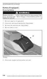
Страница 206: ...st and connected last Never charge or boost battery while in stalled on vehicle 1 Remove cargo box if applicable 2 Disconnect passenger heated grips if applicable 3 Remove seat and backrest if applica...

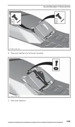
Страница 207: ...MAINTENANCE PROCEDURES mmr2017 032 002 6 Remove battery hold down bracket mmr2017 032 003 7 Remove battery _________________ 205...

Страница 208: ...attention to the following details TIGHTENING TORQUE Battery terminals positive and negative 10 N m 2 N m 89 lbf in 18 lbf in Battery hold down bracket 5 N m 0 5 N m 44 lbf in 4 lbf in Battery cover...

Страница 209: ...a mild detergent Use only microfiber cloths or an equivalent NOTICE Never use a high pressure washer to clean the vehicle USE LOW PRESSURE ONLY EX garden hose NOTICE Never use XPS Brake and Parts Clea...

Страница 210: ...Use appropriate lifting device or have assistance to share lifting stress If a lifting device is not used use proper lifting techniques notably using your legs force Do not attempt to lift the rear o...

Страница 211: ...llow the manufacturer s rec ommendations 4 Start the engine and let idle until rear heat exchanger gets hot The rear heat exchanger can be reached from under the rear end of the chassis 520002353 024_...

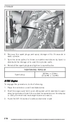
Страница 212: ...gs and tighten to specification TIGHTENING TORQUE Spark plug 28 N m 2 N m 21 lbf ft 1 lbf ft E TEC Engine To engage the procedure do the following 1 Place the vehicle in a well ventilated area 2 Start...

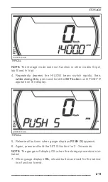
Страница 213: ...press and hold the SET button until PUSH S appears on the display 619900974 806 TYPICAL 5 Release all buttons when gauge displays PUSH S appears 6 Again press and hold the SET S button for 2 3 second...

Страница 214: ...1 minute Dur ing this time the engine RPM will increase slightly to approximately 1600 RPM and the oil pump will oil flood the engine At the end of engine lubrication procedure the ECM will turn the e...

Страница 215: ...STORAGE This page is intentionally blank _________________ 213...

Страница 216: ...STORAGE 214 _________________...

Страница 217: ...TECHNICAL INFORMATION _________________ 215...

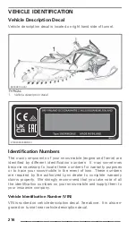
Страница 218: ...ay sometimes become necessary to locate these numbers for warranty purposes or to trace your snowmobile in the event of loss These numbers are required by the authorized Lynx dealer to complete warran...

Страница 219: ...1 000001 Model number Serial number Model year A 2010 B 2011 C 2012 etc Engine Identification Number Location 520001663 025_a 1 Engine identification number Regulation EU 2016 1628 applicable for Non...

Страница 220: ...YYYY XXXXXX SMB P V Family type e13 NRSC H CO2 g kWh Prod date EN 516010559 DEC TYPICAL NRMM IDENTIFICATION LABEL Depending on your particular vehicle configuration an additional NRMM identification l...

Страница 221: ...Products Inc 565 de la Montagne Valcourt QC Canada J0E 2L0 BRP Europe N V Skaldenstraat 125 Gent Belgium 9042 Rotax 10557 Prod date MXXXXXXX XXXX MM YYYY XXXXXX SMB P V Family type NRSC H CO2 g kWh e...

Страница 222: ...dB Uncertainty Kwa 3 dB Noise Sound pressure LpA 83 dB Uncertainty KpA 3 dB 90 dB Uncertainty KpA 3 dB 86 dB Uncertainty KpA 3 dB Hand arm system 2 5 m s2 4 3 m s2 2 5 m s2 Vibration Whole body at se...

Страница 223: ...EC DECLARATION OF CONFORMITY DoC_LYNX_MY21 _________________ 221...

Страница 224: ...EAC DECLARATION OF CONFORMITY Left blank for Eurasian Conformity mark where applicable 222 _________________...

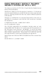
Страница 225: ...r compliance could void the user s authority to operate the equipment IC Registration Number 12006A 1001112579 FCC ID 2ACER1001112579 We the party responsible for compliance declare under our sole res...

Страница 226: ...in Maximum power engine speed 7900 100 RPM ENGINE 600R E TEC Engine type Rotax 600R E TEC liquid cooled with reed valves and electronic RAVE Number of cylinder 2 Bore 72 3 mm 2 85 in Stroke 73 mm 2 87...

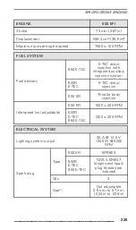
Страница 227: ...00R E TEC E TEC direct injection Fuel delivery 600 EFI Throttle body injection 600 EFI 1500 200 RPM Idle speed not adjustable 600R E TEC 850 E TEC 1200 200 RPM ELECTRICAL SYSTEM Lighting system output...

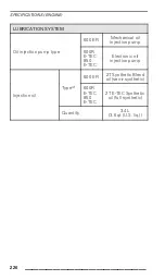
Страница 228: ...jection pump Oil injection pump type 600R E TEC 850 E TEC Electronic oil injection pump 600 EFI 2T Synthetic Blend oil semi synthetic Type 2 600R E TEC 850 E TEC 2T E TEC Synthetic oil full synthetic...

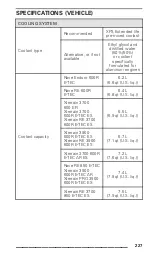
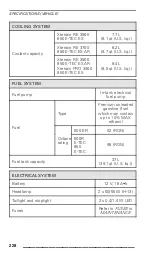
Страница 229: ...liq Rave RE 600R E TEC 6 4 L 6 8 qt U S liq Xterrain 3700 600 EFI Xterrain 3700 600R E TEC ES Xterrain RE 3700 600R E TEC ES 6 5 L 6 9 qt U S liq Xterrain 3900 600R E TEC ES Xterrain RE 3900 600R E TE...

Страница 230: ...EC ES 8 4 L 8 9 qt U S liq FUEL SYSTEM Fuel pump In tank electrical fuel pump Type Premium unleaded gasoline fuel which may contain up to 10 MAX ethanol 600 EFI 92 RON Fuel Octane rating 600R E TEC 85...

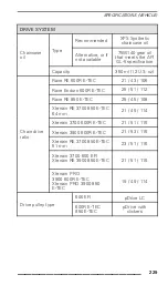
Страница 231: ...600R E TEC 25 51 112 Rave RE 850 E TEC 25 45 108 Xterrain RE 3700 850 E TEC 64 mm 21 49 114 Xterrain 3700 600R E TEC 21 51 116 Xterrain 3900 600R E TEC 21 53 116 Xterrain RE 3700 850 E TEC 51 mm 23 51...

Страница 232: ...M Driven pulley type QRS Drive sprocket number of teeth 8 Width All models 40 6 cm 16 in All 3300 326 9 cm 129 in All 3500 348 7 cm 137 in All 3700 370 5 cm 145 9 in Length All 3900 392 3 cm 154 4 in...

Страница 233: ...4 x 30 mm Caliper All other models Fixed twin pistons 2 x 40 mm Xterrain RE Ferrite Rave Enduro Metallic Brake pad material All other models Organic Rave Enduro 4 mm 2 in Minimum brake pad thickness i...

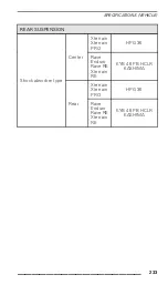
Страница 234: ...m travel Xterrain PRO 3900 215 mm 8 5 in Xterrain Xterrain PRO 3900 HPG 36 Shock absorber type Rave Enduro Rave RE Xterrain RE KYB 40 PB HCLR KASHIMA Stabilizer bar type Link REAR SUSPENSION Rave Endu...

Страница 235: ...SPENSION Xterrain Xterrain PRO HPG 36 Center Rave Enduro Rave RE Xterrain RE KYB 46 PB HCLR KASHIMA Xterrain Xterrain PRO HPG 36 Shock absorber type Rear Rave Enduro Rave RE Xterrain RE KYB 46 PB HCLR...

Страница 236: ...Ice Ripper XT 231 kg 509 3 lb Rave RE 850 E TEC 227 kg 500 4 lb Rave RE 850 E TEC Ice Ripper XT 237 kg 522 5 lb Xterrain 3700 600 EFI Xterrain 3700 600R E TEC 216 kg 476 2 lb Xterrain 3900 600R E TEC...

Страница 237: ...dry cont d Xterrain RE 3700 850 E TEC ES 64 mm AR Xterrain RE 3900 850 E TEC ES 64 mm AR 245 kg 540 1 lb Rave Enduro 302 cm 118 9 in Rave RE 313 cm 123 2 in Xterrain 3700 318 cm 125 2 in Xterrain PRO...

Страница 238: ...Xterrain PRO 3900 Rave Enduro and Rave RE 99 6 cm 2 1 cm 39 2 in 8 in Rave Enduro Rave RE 1 080 mm 42 5 in Ski stance Xterrain PRO 3900 92 1 cm 2 1 cm 36 3 in 8 in 1 NOTICE DO NOT ATTEMPT TO ADJUST G...

Страница 239: ...SPECIFICATIONS VEHICLE This page is intentionally blank _________________ 237...

Страница 240: ...SPECIFICATIONS VEHICLE 238 _________________...

Страница 241: ...TROUBLE SHOOTING _________________ 239...

Страница 242: ...M DOES NOT REACH CLUTCH ENGAGEMENT POINT 1 D E S S did not read D E S S key code in the tether cord cap D E S S pilot lamp blinks slow short beeps repetitive Properly install tether cord cap 2 D E S S...

Страница 243: ...r maintenance repair or replacement 8 Fuel pressure too low Seek service from an authorized Lynx dealer repair shop or person of your own choosing for maintenance repair or replacement ENGINE BACKFIRE...

Страница 244: ...authorized Lynx dealer repair shop or person of your own choosing for maintenance repair or replacement HEATED GRIPS THUMB WARMERS ARE NOT WORKING 1 Engine RPM is too low Make sure engine RPM is abov...

Страница 245: ...09 TYPICAL PILOT LAMPS Pilot lamp can flash alone or in combination with another lamp On the multifunction analog digital gauge the center display is used as a complement of the pilot lamps to give yo...

Страница 246: ...SAGE DISPLAY DESCRIPTION HIGH ENGINE TEMPERATURE Engine is overheating reduce snowmobile speed and run in loose snow or stop engine immediately and let engine cool down Check coolant level refer to MA...

Страница 247: ...ool down If overheating persists contact an authorized Ski Doo dealer Do not run the engine if condition persists BATT VOLT Indicate a low or high battery voltage condition See an authorized Ski Doo d...

Страница 248: ...ready to operate WRONG KEY Unable to read key bad connection Make sure the key is clean and correctly snapped on post DESS CHECK KEY Invalid key or key not programmed Use the proper key for the vehic...

Страница 249: ...WARRANTY _____ 247...

Страница 250: ...the snowmo bile was used for racing or any other competitive activity at any point even by a previous owner or 2 the snowmobile has been altered or modified in such a way so as to adversely affect its...

Страница 251: ...judgement are either incompatible with the product or adversely affect its operation performance and durability or resulting from repairs done by a person that is not an authorized servicing LYNX Dist...

Страница 252: ...nty guarantee right or remedy conferred or implied under the Competition and Consumer Act 2010 Cth including the Australian Consumer Law or any other law where to do so would contravene that law or ca...

Страница 253: ...The customer must notify a servicing LYNX Distributor Dealer within two 2 days of the appearance of a defect and provide it with reasonable access to the product and reasonable opportunity to repair i...

Страница 254: ...ions shall also be transferred and be valid for the remaining coverage pe riod provided BRP or an authorized LYNX Distributor Dealer receives a proof that the former owner agreed to the transfer of ow...

Страница 255: ...limited warranty will become null and void if 1 the snowmo bile was used for racing or any other competitive activity at any point even by a previous owner or 2 the snowmobile has been altered or mod...

Страница 256: ...udgement are either incompatible with the product or adversely affect its operation performance and durability or resulting from repairs done by a person that is not an authorized servicing LYNX Distr...

Страница 257: ...its original expiration date Note that the duration and any other modalities of the warranty cov erage are subject to the applicable national or local legislation in the customer s country 5 CONDITION...

Страница 258: ...T BRP WILL DO To the extent permitted by law BRP s obligations under this warranty are limited to at its sole discretion repairing parts found defective under normal use maintenance and service or rep...

Страница 259: ...ted warranty BRP suggests that you try to resolve the issue at the LYNX Distributor Dealer level We recommend discussing the issue with the authorized LYNX Distributor Dealer s service manager or owne...

Страница 260: ...le or model Have the qualities that a buyer may legitimately expect considering the public declarations of the seller the manufacturer of its representative including in advertising or labeling or 2 H...

Страница 261: ...re Print Mileage km Hours Date Dealer no Notes Refer to vehicle Pre Delivery Bulletin for detailed installation procedures FIRST INSPECTION Mileage km Signature Print Hours Date Dealer no Notes For ma...

Страница 262: ...r maintenance schedule refer to Maintenance Information section of this operator s guide SERVICE Mileage km Signature Print Hours Date Dealer no Notes For maintenance schedule refer to Maintenance Inf...

Страница 263: ...r maintenance schedule refer to Maintenance Information section of this operator s guide SERVICE Mileage km Signature Print Hours Date Dealer no Notes For maintenance schedule refer to Maintenance Inf...

Страница 264: ...r maintenance schedule refer to Maintenance Information section of this operator s guide SERVICE Mileage km Signature Print Hours Date Dealer no Notes For maintenance schedule refer to Maintenance Inf...

Страница 265: ...r maintenance schedule refer to Maintenance Information section of this operator s guide SERVICE Mileage km Signature Print Hours Date Dealer no Notes For maintenance schedule refer to Maintenance Inf...

Страница 266: ...r maintenance schedule refer to Maintenance Information section of this operator s guide SERVICE Mileage km Signature Print Hours Date Dealer no Notes For maintenance schedule refer to Maintenance Inf...

Страница 267: ...CUSTOMER INFORMATION _____ 265...

Страница 268: ...er list to distribute marketing and pro motional information about BRP and related products To exercise your right to consult or correct your data or to be re moved from the addressee list for direct...

Страница 269: ...o 108 0075 Japan Europe Skaldenstraat 125 B 9042 Gent Belgium Itterpark 11 D 40724 Hilden Germany ARTEPARC B timent B Route de la c te d Azur Le Canet 13590 Meyreuil France Ingvald Ystgaardsvei 15 N 7...

Страница 270: ...20 Santa Rosa J uregui Qro Mexico Sturtevant Wisconsin U S A 10101 Science Drive Sturtevant Wisconsin 53177 U S A Oceania 6 Lord Street Lakes Business Park Botany NSW 2019 Australia 3B Echelon Place E...

Страница 271: ...e In case of change of ownership please join a proof that the former owner agreed to the transfer Notifying BRP even after the expiration of the limited warranty is very important as it enables BRP to...

Страница 272: ...CHANGE OF ADDRESS OWNERSHIP This page is intentionally blank 270 _________________...

Страница 273: ...CHANGE OF ADDRESS OWNERSHIP CHANGEADD SKI _________________ 271...

Страница 274: ...CHANGE OF ADDRESS OWNERSHIP This page is intentionally blank 272 _________________...

Страница 275: ...CHANGE OF ADDRESS OWNERSHIP CHANGEADD SKI _________________ 273...

Страница 276: ...CHANGE OF ADDRESS OWNERSHIP This page is intentionally blank 274 _________________...

Страница 277: ...CHANGE OF ADDRESS OWNERSHIP CHANGEADD SKI _________________ 275...

Страница 278: ...CHANGE OF ADDRESS OWNERSHIP This page is intentionally blank 276 _________________...

Страница 279: ...CHANGE OF ADDRESS OWNERSHIP NOTES _________________ 277...

Страница 280: ...CHANGE OF ADDRESS OWNERSHIP NOTES 278 _________________...

Страница 281: ...CHANGE OF ADDRESS OWNERSHIP NOTES _________________ 279...

Страница 282: ...CHANGE OF ADDRESS OWNERSHIP NOTES 280 _________________...

Страница 283: ...AND THE BRP LOGO ARE TRADEMARKS OF BOMBARDIER RECREATIONAL PRODUCTS INC OR ITS AFFILIATES 2020 BOMBARDIER RECREATIONAL PRODUCTS INC ALL RIGHTS RESERVED WARNING BEFORE YOU OPERATE THIS VEHICLE READ TH...

Отзывы: