IO-390-D Series Engine Maintenance Manual
72-20
© 2020 Avco Corporation. All Rights Reserved
Page 158
March 2020
IO-390-D Series Engine Maintenance Manual
(8)
Remove and discard the alignment dowel.
(9)
Examine the bottom of the alignment dowel hole to make sure that the drill bit did not
make contact with the bottom of the hole. If the drill bit made contact with the bottom of
the hole, send the crankshaft to the factory for evaluation.
(10)
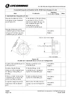
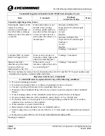
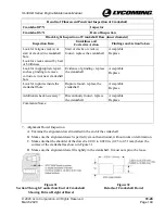
Press the replacement alignment dowel into the alignment dowel hole to the required
driven height. Refer to Figure 43 or the latest revision of Service Bulletin No. SB-475
and its supplements for the alignment dowel part number and the correct driven height.
B.
Crankshaft Gear Installation
(1)
Start with a clean crankshaft that passed the “Crankshaft Inspection” in this chapter.
(2)
Make sure the mating surfaces of the crankshaft gear and crankshaft counter-bored end
are clean and dry and that there is no debris. Refer to the procedure “Crankshaft
Cleaning” and Crankshaft Counterbore Cleaning” in Chapter 5-30 in this manual.
(3)
Install the crankshaft (with the counter-bored end vertically upright) securely in a holder.
(4)
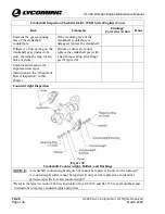
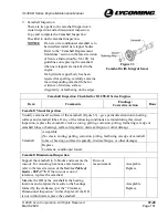
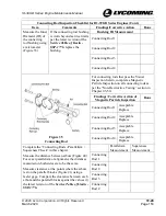
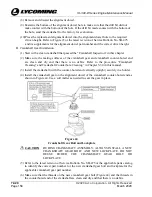
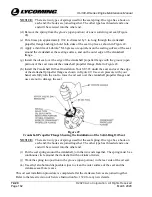
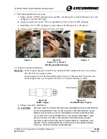
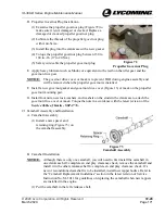
Install the crankshaft gear on the alignment dowel of the crankshaft counter-bored end as
shown in Figure 44. Use a soft mallet as needed to seat the gear in place.
Figure 44
Crankshaft Gear Bolt and Lockplate
CAUTION
DURING CRANKSHAFT ASSEMBLY, ALWAYS INSTALL A NEW
CRANKSHAFT GEAR BOLT AND NEW LOCKPLATE. DO NOT
REUSE
EITHER
THE
CRANKSHAFT
GEAR
BOLT
OR
LOCKPLATE.
(5)
Refer to the latest revision of Service Bulletin No. SB-475 or the applicable parts catalog
to identify the correct part number for the new crankshaft gear bolt and lockplate for the
applicable crankshaft gear part number.
(6)
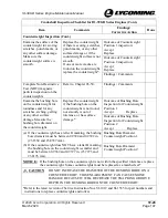
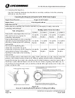
Make sure that the threads on the new crankshaft gear bolt (Figure 44) and the threads in
the counterbored end of the crankshaft are clean and dry and that there is no debris.

