Operating Modes
Version 6.03, May 2017
Page 57 of 192
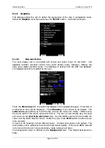
5.1.6.4
Glider and Track
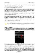
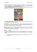
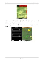
Navigational screen can show the coloured path flown, current track vector and target
vector with terrain collision warning.
Check the
Show path
item if you want to see the flown path.
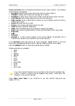
Path length
defines how
much of the flown path will be shown. The path can be coloured using:
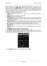
Fixed
path style. Path colour is fixed and defined by path colour item.
Mc
path style, which is based on current MacCready settings. Red colour indicates
segments of the flight where we have vertical speed higher than the current MacCready
setting. Orange colour shows vertical movements similar to the current MacCready
setting and blue for vario values below the MacCready setting. Grey depicts sink areas.
Vario
path style, where red colour indicates positive vertical speed and blue colour
negative vario values.
Altitude
path style, where red colour means low altitude and blue means high altitude.
Ground speed
path style, where red colour means slow speed and blue colour means
fast speed.
Netto
path style, where red colour indicates positive netto vertical speed and blue
colour negative netto values.
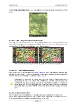
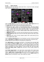
Check the
Show current track
item if you would like to see your current ground track
vector.
Track colour
and
width
defines the colour and width of the current track vector.
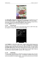
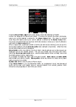
Selected target and current position are connected with a magenta line.
Check
Show target
if you would like to see this line. In the target colour and target width
you can select the
Colour
and
Width
of this line. You can also choose to show or hide the
terrain collision point and the target line itself. The terrain collision marker is a red square
which is only displayed when there is terrain between the navigational point and the current
position and therefore not enough altitude to reach the target with the current glider
settings.
Font Style
,
Colour
and
Size
define what font for terrain collision altitude and
range circles.
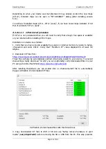
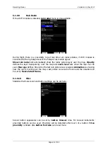
Enable
Show range circles
to plot range circles around aircraft symbol. Having range
circles on navigational screen, it is much easier to guess distance to nearest point of
interest.
Range colour
and
range width
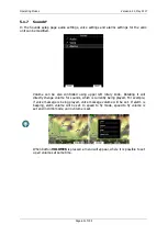
define the way circles are rendered. A built in
engine noise level sensor detects, if engine is running or not. Use
Engine colour
and
width
properties to visualize part of path, where engine was running.

