Lumel N10A Скачать руководство пользователя страница 1

POWER NETWORK  

PARAMETER  

ANALYSER 

N10A

SERVICE MANUAL

Содержание N10A

Страница 1: ...POWER NETWORK PARAMETER ANALYSER N10A SERVICE MANUAL...

Страница 2: ......

Страница 3: ...ACEPLATE DESCRIPTION 13 4 2 N10A OPERATING MODES 14 4 2 1 MEASURING MODE 15 4 2 1 1 Measurement of voltage and current harmonics 16 4 2 2 TIME SETTING MODE t 17 4 2 3 PARAMETER CONFIGURATION MODE S 17...

Страница 4: ......

Страница 5: ...tiplied by voltage and current ratios of measuring transducers what is taking in consideration in calculations and indications of power and energy The meter shows also the real time The RS 485 interfa...

Страница 6: ...e 1 pc lead of the RS 485 interface 1 pc matching resistor 1 pc diskette for the WIZPAR program 1 pc 3 INSTALLATION 3 1 Fitting way The meter is adapted to be mounted by means of holders according fig...

Страница 7: ...Fig 1 Overall dimensions and fitting way of the N10A meter...

Страница 8: ...3 2 External connection diagrams Direct measurement in a 3 phase network Half intermediate measurement in a 3 phase network...

Страница 9: ...Fig 2 Meter connection diagrams in a three phase network Intermediate measurement using 2 current transformers and 2 or 3 voltage trans formers in a 3 phase network...

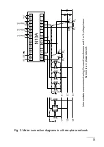
Страница 10: ...10 Direct measurement in a 4 wire network Half intermediate measurement in a 4 wire network...

Страница 11: ...11 Fig 3 Meter connection diagrams in a four wire network Intermediate measurement using 2 current transformers and 2 or 3 voltage trans formers in a 4 wire network...

Страница 12: ...ion it is recommended to use a double wire twisted conductor in a shield The shield should be connected to the earth in one point The shield is necessary when the environment is very perturbed Fig 4 C...

Страница 13: ...parameter units Values of measured parameters are shown on active pages selected by successive pressures of the key A page consists of 4 optional quantities chosen from the table 5 and displayed simu...

Страница 14: ...isplay luminosity in the setup procedure Key This key enables in anytime the resignation of carried out operations It cancels alarms in measuring mode 4 2 N10A operating modes The N10A meter has 5 ope...

Страница 15: ...of the suitable symbol Accept the chosen mode by the key The return from other modes into the measuring mode is carried out by means of the or key after the last parameter in t S and A modes after the...

Страница 16: ...by the or key the required quantity and press the key The following quantities will be displayed Where w n chosen quantity e g U 1 n n harmonic number xxx x value of the n th harmonic The harmonic num...

Страница 17: ...sition to hours and minutes settings Where yyyy year mm month dd day The setting of hours and minutes is similar to the setting of the year month and day after min minutes causes the memorization of s...

Страница 18: ...ntinuous output Ao_n 0 34 Quantity code acc table 5 Cancellation of the active energy counter EnP0 Y n n Cancellation of the reactive energy counter Enq0 Y n n Cancellation of the apparent energy coun...

Страница 19: ...measuring mode causes the setting on the successive parameter after the last parameter causes the memorization of setting values and the exit from the mode S Notice PA_S Y means that the average powe...

Страница 20: ...120 0 120 Ao_3 0 off Quantity on the continuous output nr 3 0 1 34 Quantity code acc table 5 AoL3 100 Lower value of the input range 120 0 120 Upper value of the input range AoH3 120 0 120 The entry...

Страница 21: ...Code Quantity name Symbol Unit Signalling Mark 00 Without quantity display extinguished 01 Phase 1 voltage U1 k V L1 02 Line L1 curren I1 k A L1 03 Phase L1 active power P1 M k W L1 04 Phase L1 reacti...

Страница 22: ...M k Wh L1 L2 L3 36 3 phase reactive energy Enb M k VArh L1 L2 L3 37 3 phase apparent energy EnS M k VAh L1 L2 L3 38 Active energy from external counter EnPz M k Wh 39 Reactive energy from external co...

Страница 23: ...k V 31 U23 k V 32 U31 k V 33 U123 k V Page 1 Page 2 Page 3 Page 4 02 I1 k A 09 I2 k A 16 I3 k A 23 Is k A 24 P Mk W 25 Q Mk VAr 26 S Mk VA 27 Pf 35 EnP Mk Wh 36 EnB Mk VArh 37 EnS Mk VAh 38 f 41 dd m...

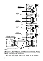
Страница 24: ...24 Fig 6 N10A meter working modes...

Страница 25: ...xtremal values Lo F frequency lower than 47 Hz for THD Ui THD Ii measurements Hi F frequency higher than 52 Hz for THD Ui THD Ii measurements 6 TECHNICAL DATA Measuring ranges and admissible basic err...

Страница 26: ...ctor 1 00 0 00 1 000 1 m v 2c Error in the range 99 9 0 99 9 tg i factor ratio of reactive power to active power 99 9 0 99 9 1 m v 2c 0 5 m v f frequency 15 0 500 0 Hz Where Ku voltage transformer rat...

Страница 27: ...al operation conditions Input signal 0 0 01 1 2 In 0 0 01 1 2 Un for voltage current frequency power and energy 0 0 02 1 2 In 0 0 07 1 2 Un for Pf and t factors frequency 15 45 65 500 Hz sinusoidal in...

Страница 28: ...50 10 C Electromagnetic compatibility immunity acc EN 61000 6 2 emission acc EN 61000 6 4 Safety requirements acc EN 61010 1 A1 insulation ensured by the housing dual insulation between circuits basic...

Страница 29: ...0 with RS 485 interface 1 Displays red digits 1 green digits 2 Power supply 85 250 V d c a c 40 400 Hz 0 acc order 9 Version standard 00 custom made 99 Acceptance test without additional requirements...

Страница 30: ...meter down from the installation and return it to the LUMEL s Quality Control Dept If the unit has been used in compliance with the instructions LUMEL S A warrants to repair it free of charge 2 After...

Страница 31: ...31...

Страница 32: ...AMP ON METERS INDUSTRIAL and HOUSEHOLD CONTROLLERS CHART AND PAPERLESS RECORDERS POWER CONTROL UNITS and INVERTERS LARGE SIZE NUMERIC and ALPHANUMERIC DISPLAYS AUTOMOTIVE DASHBOARD INDICATORS ACCESSOR...

Отзывы: