ISDN DEFINITY
Extender 2300EU/2100EU
50
Troubleshooting
LED
Sequences
The LED sequences on the Switch and Remote Modules
are indicators of the status of the extenders during power
up. Please refer to the tables below if you experience
problems when powering up.
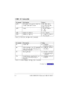
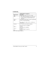
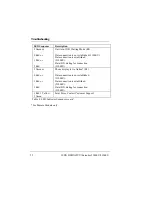
LED Power Up Sequences
LED Sequence
Description
No LED blinks
Error with hardware or AC adapter.
First blink:
Red or Green
LED is not functioning properly as units should blink
Yellow.
Yellow
EPROM Checksum test failed. Faulty EPROM or
Board problem.
Yellow & 1 Red
DRAM, Data test failed
Yellow & 2 Red
DRAM Address test failed
Yellow & 3 Red
DUART, test failed.
Yellow & 7 Reds
& 1 Green
Passed all hardware tests
Table 6. LED Power Up Sequences
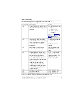
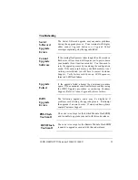
LED Power Up Verification Sequences
LED Sequence
Description
Rapidly blinking
Red during
process and then 1
Green to indicate
process is
complete.
•
10 - 15 seconds. FLASH code is being verified and
if valid will be executed.
•
25-30 seconds FLASH code is invalid EPROM
code copied to FLASH.
3 Reds or 3
Greens followed
by a Red.
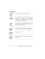
•
Red – Running EPROM code, FLASH write failed.
Contact Customer Service.
•
Green – FLASH load passed, running FLASH
code.
3 sets of 8
Yellow blinks
Access terminal configuration menu by typing
‘MENU’.
Table 7. LED Power Up Verification Sequences

