M10P
12
6.1
Hardware Connection and Test
1)
Connect the lidar to the internet and power supply
2)
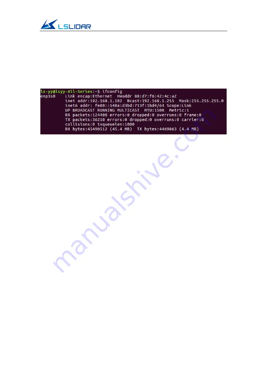
Set the computer wired IP according to the destination IP of the lidar (you
can use the ifconfig command to check whether the computer wired IP is
set successfully. As shown in the figure, the destination IP is 192.168.1.102)
Figure 6.1 ifconfig Command Feedback
Note:
The default destination IP of the lidar is 192.168.1.102, and the computer
must be configured according to the actual Lidar destination IP. (By default, the
lidar is not activated when powered up.)
3)
After the lidar is powered on, open a new terminal and input the starting
instruction: rostopic pub -1 /lslidar_difop_switch std_msgs/Int8 "data: 1".
Then the lidar starts scanning.
4)
After the lidar is powered on and started, check the wired connection icon
of the computer to see whether it is connected properly.
5)
Open the terminal: ping the lidar IP, and test whether the hardware is
connected normally. If the ping is successful, then the data is received,
otherwise check the hardware connection.
6)
Use “sudo tcpdump -n -i eth3s0” (here eth3s0 is the name of the wired
network device, see the device name of ifconfig wired connection display
for details) to view the data packets sent by the lidar (as shown in the figure,
there are 1206-byte data packets sent by the Lidar to the destination, which
means that the lidar data is sent normally).
7)
If you want to stop the lidar, please input the stop instruction: rostopic pub
-1 /lslidar_difop_switch std_msgs/Int8 "data: 0".


