3-4
Interfaces
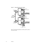
Figure 3.1
Analog I/Q Output Interface Diagram
Figure 3.2 shows a typical application for interfacing with the outputs of
the two L64777 DACs.
AVDD1/COMP1
Vref1
10-Bit DAC
10
AVSS2
AVDD2COMP2
Differential Q Output
Differential I Output
VSS
AVSS1
R
VDDX1
3
On-Chip
Off-Chip
QAM_I, QAM_In
QAM_Q, QAM_Qn
Q Filter Output
I Filter Output
Functional
(Test mode is
selected using
Vref2
VDDX2
10
10-Bit DAC
R
3
2
10
Test Bus
FT mode pins)
Содержание L64777
Страница 1: ...L64777 DVB QAM Modulator Order Number I14031 A Technical Manual June 2000...
Страница 10: ...x Contents...
Страница 14: ...1 4 Introduction...
Страница 90: ...5 10 Signals...
Страница 110: ...A 8 Programming the L64777 in Serial Host Interface Mode...
Страница 116: ...C 2 Monitoring Device Internal Signals...
Страница 124: ......


