


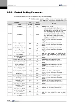

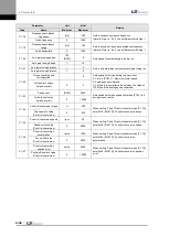
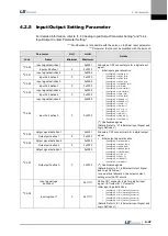


4. Parameters
4-24
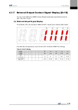
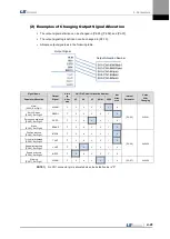
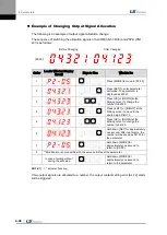
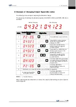
(4)
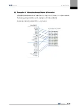
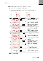
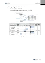
Examples of Changing Output Singal Logic Definition
Output signal logic definitions can be changed at [P2-10]
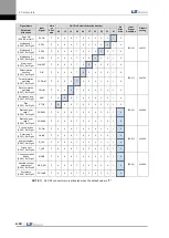
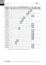
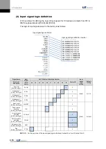
Set output singals as shown in the table below when they are allocated as below.
Signal Name
Input
Signal
(Initial
Name)
CN1 Pin Default Allocation Number
Contact B
Output
Signal
Logic
Definition
Default
Setting
Parameter Allocation
45
44
43
40 /41
38 /39
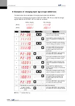
Alarm
[P2-10].Set Digit 1
ALARM
0
[P2-10]
0x11110
Servo Ready
[P2-10]. Set Digit 2
READY
1
0
Zero speed achieved
[P2-10].Digit 3
ZSPD
1
0
Brake
[P2-10].Digit 4
BRAKE
1
0
Position reached
[P2-10].Digit 5
INPOS
1
0
For the purpose of the input signal logic definition, Contact A is 1 and Contact B is 0
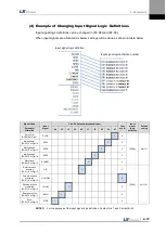
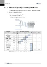
Output signal logic definitions
Output signal logic definition number
DO1(Contact A/Contact B)
DO2(Contact A/Contact B)
DO3(Contact A/Contact B)
DO4(Contact A/Contact B)
DO5(Contact A/Contact B)
Содержание L7 A001
Страница 1: ...VER 1 5...
Страница 2: ......
Страница 32: ...1 Product Components and Signals 1 20...
Страница 38: ...2 Installation 2 6...
Страница 54: ......
Страница 188: ...7 Product Specifications 7 26 L7 A020 L7 A035 Weight 2 5 kg cooling fan included...
Страница 210: ...8 Maintenance and Inspection 8 14...
Страница 211: ...9 Appendix 9 1 9 Appendix...
Страница 218: ...9 Appendix 9 8...
Страница 221: ......
Страница 222: ......