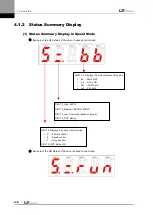
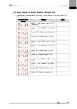

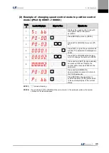
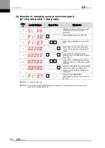


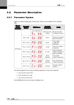


4. Parameters
4-16
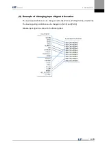
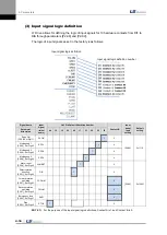
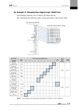
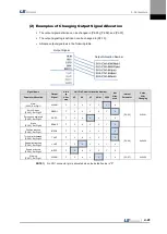
(3)
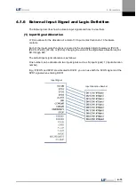
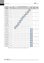
Input signal logic definition
L7 Drive allows for defining the logic of input signals for 10 hardware contacts from DI1 to
DIA through parameters [P2-08] and [P2-09].
The logic of input signals as set in the factory is as follows.
Signal Name
Input
Signal
(Initial
name)
CN1 Pin Default Allocation Number
Contact B
Input
signal
logic
setting
Default
setting
Parameter
Allocation
48
18
19
20
46
17
21
22
23
47
Servo ON
[P2-08].Set Digit 1
SVON
1
0
[P2-08]
0x11111
Multi-speed 1
[P2-08]. Set Digit 2
SPD1
1
0
Multi-speed 2
[P2-08]. Set Digit 3
SPD2
1
0
Multi-speed 3
[P2-08]. Set Digit 4
SPD3
1
0
Alarm reset
[P2-08]. Set Digit 5
ALMRST
1
0
[P2-09]
0x10001
Select rotation
direction
[P2-01]. Set Digit 2
DIR
1
0
Forward rotation
prohibited
[P2-01]. Set Digit 3
CCWLIM
0
Reverse rotation
prohibited
[P2-01]. Set Digit 4
CWLIM
0
Emergency stop
[P2-02]. Set Digit 1
EMG
0
Stop
[P2-02]. Set Digit 2
STOP
1
0
NOTE 1)
For the purpose of the input signal logic definitions, Contact A is 1 and Contact B is 0.
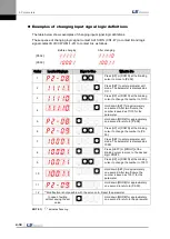
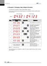
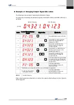
Input signal logic definition
Input signal logic definition number
Содержание L7 A001
Страница 1: ...VER 1 5...
Страница 2: ......
Страница 32: ...1 Product Components and Signals 1 20...
Страница 38: ...2 Installation 2 6...
Страница 54: ......
Страница 188: ...7 Product Specifications 7 26 L7 A020 L7 A035 Weight 2 5 kg cooling fan included...
Страница 210: ...8 Maintenance and Inspection 8 14...
Страница 211: ...9 Appendix 9 1 9 Appendix...
Страница 218: ...9 Appendix 9 8...
Страница 221: ......
Страница 222: ......