4. Parameters
4-11
4.1.6
External Input Signal and Logic Definition
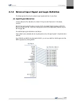
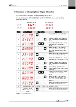
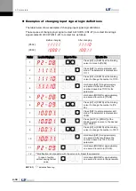
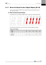
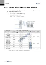
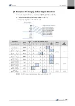
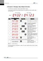
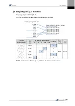
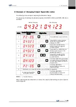
The following describes how to allocate input signals and how to view them.
(1)
Input Signal Allocation
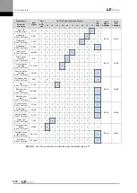
L7 Drive allows for the allocation of a total of 19 input contact fuctions to 10 hardware
contacts.
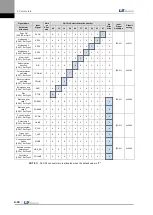
Each of the input contact functions is located at the designated digit of parameter [P2-00],
[P2-01], [P2-02], [P2-03], or [P2-04]. Changing the value of the digit allows allocation to pins
DI1 through DIA
The default input signal allocation is as follows:
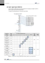
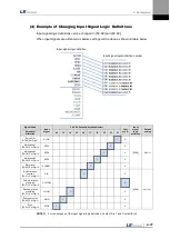
One number can be allocated to two input signals such as N (input signal): 1 (input allocation
number).
E.g.) If SVON and SPD1 are allocated to DI #01, you can use both the SVON signal and the
SPD1 signal when entering DI #01.
Input Signal
Input Allocation Number
Содержание L7 A001
Страница 1: ...VER 1 5...
Страница 2: ......
Страница 32: ...1 Product Components and Signals 1 20...
Страница 38: ...2 Installation 2 6...
Страница 54: ......
Страница 188: ...7 Product Specifications 7 26 L7 A020 L7 A035 Weight 2 5 kg cooling fan included...
Страница 210: ...8 Maintenance and Inspection 8 14...
Страница 211: ...9 Appendix 9 1 9 Appendix...
Страница 218: ...9 Appendix 9 8...
Страница 221: ......
Страница 222: ......

